4
z
•
Unauthorized reproduction or copying of all or part of this manual is
prohibited.
z
•
Oriental Motor shall not be liable whatsoever for any problems relating
to industrial property rights arising from use of any information, circuit,
equipment or device provided or referenced in this manual.
z
•
Characteristics, specifications and dimensions are subject to change without
notice.
z
•
While we make every effort to offer accurate information in the manual, we
welcome your input. Should you find unclear descriptions, errors or omissions,
please contact the nearest office.
z
•
is a registered trademark or trademark of Oriental Motor Co.,
Ltd., in Japan and other countries.
© Copyright ORIENTAL MOTOR CO., LTD. 2012
Published in November 2017
Technical Support Tel:(800)468-3982
8:30
A.M.
to 5:00
P.M.
, P.S.T. (M-F)
7:30
A.M.
to 5:00
P.M.
, C.S.T. (M-F)
www.orientalmotor.com
Schiessstraße 44, 40549 Düsseldorf, Germany
Technical Support Tel:00 800/22 55 66 22
www.orientalmotor.de
Tel:01256-347090
www.oriental-motor.co.uk
Tel:01 47 86 97 50
www.orientalmotor.fr
Tel:02-93906346
www.orientalmotor.it
Tel:+55-11-3266-6018
www.orientalmotor.com.br
• Please contact your nearest Oriental Motor office for further information.
4-8-1Higashiueno,Taito-ku,Tokyo 110-8536
Japan
Tel:03-6744-0361
www.orientalmotor.co.jp
Tel:0800-060708
www.orientalmotor.com.tw
Singapore
Tel:1800-8420280
www.orientalmotor.com.sg
Tel:1800-806161
www.orientalmotor.com.my
Korea
Tel:080-777-2042
www.inaom.co.kr
Tel:1800-888-881
www.orientalmotor.co.th
Tel:400-820-6516
www.orientalmotor.com.cn
Tel:+91-80-41125586
www.orientalmotor.co.in
Hong Kong Branch
Tel:+852-2427-9800
Three-phase motors
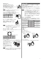
Connect the motor according to the
figure. When connected according to the
connection diagram, the motor will
operate in the clockwise direction (CW) as
viewed from the motor’s output shaft.
To change the direction of rotation,change
any two connections between R, S and T.
Red
White
L1(R)
L2(S)
L3(T)
Black
Motor
PE
CW
Connecting Protective Earth Terminal
Ground the motor using the motors with a Protective Earth Terminal .
Applicable crimp terminal:
Insulated round crimp terminal
Terminal screw size: M4
Tightening torque:
1.0 to 1.3 N·m (8.8 to 11.5 lb-in)
Applicable minimum lead wire size:
AWG18 (0.75 mm
2
) or more
Unit [mm (in.)]
Ø4.1 (0.16) min.
4.8 (0.19) max.
9.5 (0.37) max.
Note
Do not use screws other than the Protective Earth Terminal screws
attached on the product.
Time rating
Note
The continuous-operation time when operating the motors with the
speed controllers depends on the load, set speed and operating
cycle.
z
z
Induction motors
Induction motors have a continuous rating.
z
z
Reversible motors
Reversible motors have a 30 minutes rating. “30 min” is indicated on the
nameplate.
Locked rotor burnout protection
This motor is equipped with one of the two features listed below to prevent the
motor from burning out as a result of abnormal heating which may be caused by
misapplication.
Thermal protection
“TP” is stamped on the motor nameplate. The motor has an “auto reset”
type thermal protector built into its motor coil. When the motor reaches a
predetermined temperature, the internal thermal protector is activated and the
motor is stopped.
Always turn the power off before performing inspections.
Thermal protector activation range:
Power is turned off at 130±5 °C (266±9 °F)
Power is turned back on at 85±20 °C (185±36 °F)
Impedance protection
“ZP” is stamped on the motor nameplate. The motor has higher coil impedance.
When the motor goes into locked rotor condition due to a malfunction, coil
impedance rises, suppressing input power to the motor and protecting the motor
coil from burnout.
Troubleshooting
When the motor cannot be operated correctly, refer to the contents provided in
this section and take appropriate action. Refer also to the OPERATING MANUAL
for the speed controller. If the problem persists, contact your nearest office.
Phenomena
Check items
Motor does not rotate.
z
•
Check the power supply voltage.
z
•
Connect the power supply and the motor correctly.
z
•
Speed control motors connect correctly by
referring to the OPERATING MANUAL for the
speed controller.
z
•
With a single-phase motor, connect the supplied
capacitor correctly.
z
•
If terminal blocks or crimp terminals are used,
check them for poor connection.
z
•
Keep the load at or below the allowable value.
Phenomena
Check items
Motor sometimes rotates
and stops.
z
•
Connect the power supply and the motor correctly.
z
•
Speed control motors connect correctly by
referring to the OPERATING MANUAL for the
speed controller.
z
•
With a single-phase motor, connect the supplied
capacitor correctly.
z
•
If terminal blocks or crimp terminals are used,
check them for poor connection.
The motor rotates in the
direction opposite to the
specified direction.
z
•
Speed control motors connect correctly by
referring to the OPERATING MANUAL for the
speed controller.
z
•
With a single-phase motor, connect the supplied
capacitor correctly.
z
•
The rotating direction of the motor output shaft
may be different from that of the gearhead output
shaft depending on the gear ratio of the gearhead.
See "Rotating direction of the gearhead output
z
•
The rotating direction is indicated as viewed
from the motor output shaft. Check the reference
direction.
Motor temperature
abnormally high
[Motor case temperature
exceeds 90 °C (194 °F)]
z
•
Check the power supply voltage.
z
•
With a single-phase motor, connect the supplied
capacitor correctly.
z
•
Review the ventilation condition.
Noisy operation
z
•
Assemble the motor and gearhead correctly by
referring to the OPERATING MANUAL for the
gearhead.
z
•
Assemble a gearhead of the same pinion type as
the motor.

