EN
7.
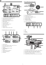
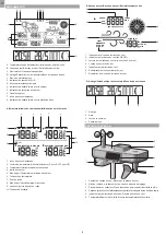
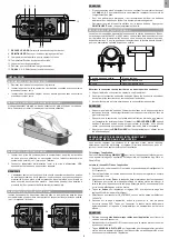
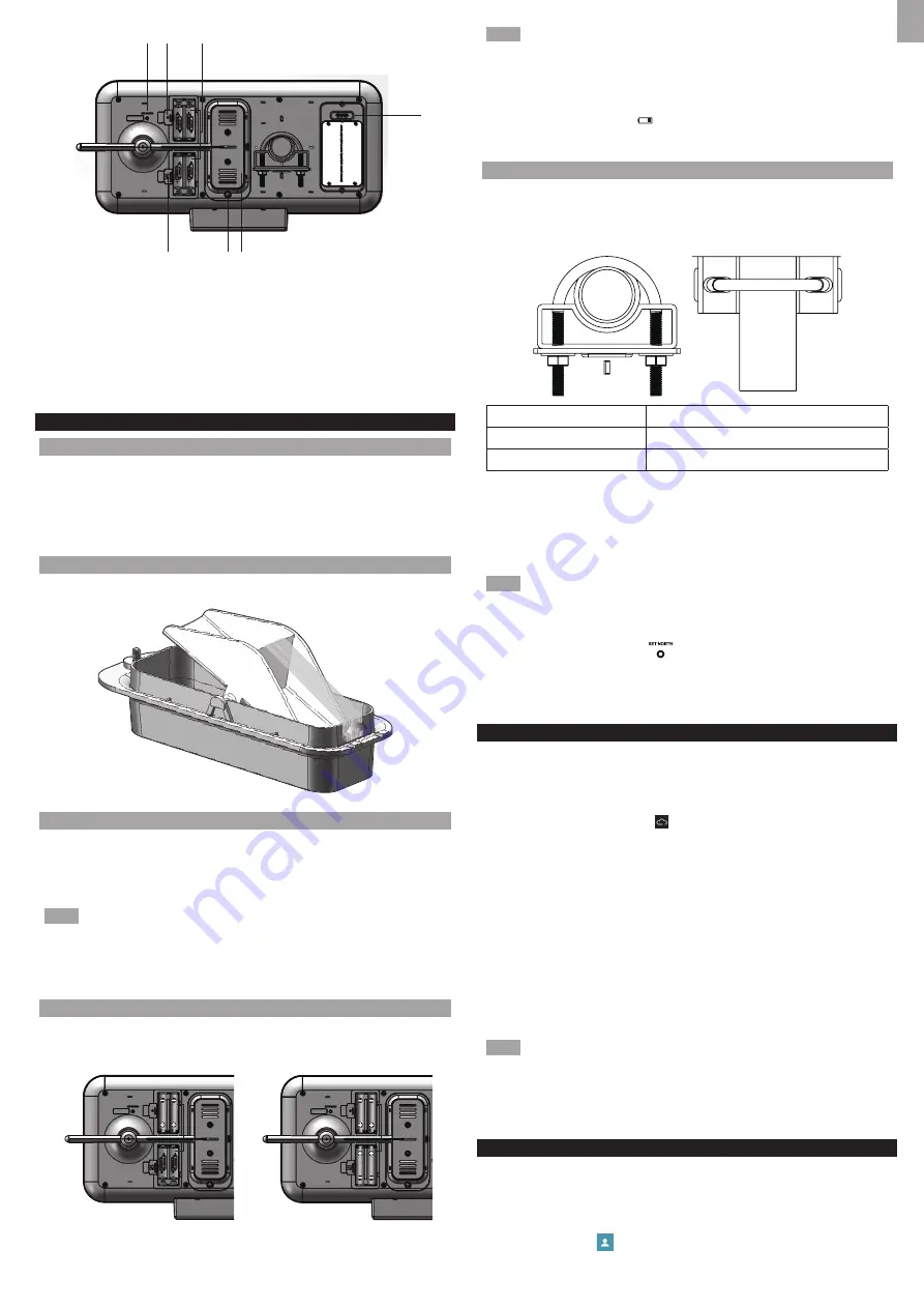
SET NORTH
: Calibrates the direction of wind sensor
8.
RESET
: Returns unit to default settings
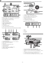
9. Battery compartment for the all-in-one sensor
10. Temperature/Humidity sensor location
11. Housing for tipping bucket
12. Screw to open/close the tipping bucket
13.
CHANNEL 1, 2, 3
: Select sensor channel
INSTALLATION
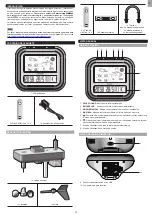
ASSEMBLE THE WIND SENSOR
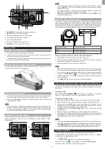
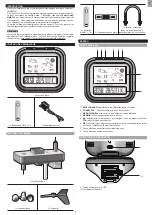
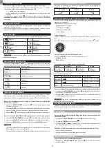
1. Loosen the screws in the wind cups and wind vane.
2. Insert the top of the wind sensor unit into the wind cups securely with some
pressure and then twist the screw tightly.
3. Insert the bottom of the wind sensor unit into the wind vane securely with some
pressure and then twist the screw tightly.
REMOVE THE TAPE ON THE TIPPING BUCKET
A tipping bucket is located under the rain collector and fixed by fiber tape. Unscrew it
and remove the tape before first time using.
POWER THE BASE STATION
1. Insert the 3 AA batteries (included) to the battery compartment of the base station
for back-up usage, matching the polarity symbols (+ and -) marked inside.
2. Connect the supplied power adapter to the Micro USB power jack, and then plug
into a standard AC out
let.
NOTE
• The power adapter is intended to be correctly oriented in a vertical or floor mount
position. The prongs are not designed to hold the plug in place if it is plugged into
a ceiling, under-the-table or cabinet outlet. The socket-outlet shall be installed
near the equipment and shall be easily accessible.
POWER THE ALL-IN-ONE SENSOR
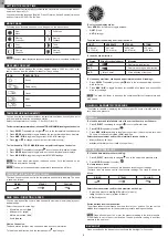
Insert 4 batteries into one of the battery compartments or insert 8 batteries into two
battery compartments at the same time
,
matching the polarity symbols (
+
and
-
)
marked inside.
7
8
9
10
11
12
13
NOTE
•
If you will be connecting more than one all-in-on sensor, slide the channel
switch
CHANNEL 1, 2, 3
to select another channel before replacing the battery
compartment cover.
•
For longer performance, recommend to use alkaline batteries and consumer
grade lithium batteries in temperatures below freezing.
• R
eplace the batteries when displays on the base station. Press
RESET
after
each battery replacement.
MOUNTING THE ALL-IN-ONE SENSOR
The sensor is capable of transmitting data to the base station wirelessly within an
approximate operating range of 300 m (1000 feet). Ideal locations for the sensor would
be in any location on the roof of a building that is in an open area away from trees or
other obstructions preventing from the wind flow for an accurate reading. Additionally,
locate the sensor in direct sunlight for optimal power supply to the solar panel.
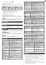
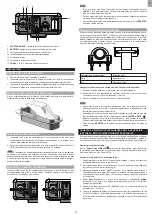
Solar panel facing:
If you reside in the:
North
Southern Hemisphere
South
Northern Hemisphere
Secure the all-in-one sensor connector in the desired location:
1. Align the back of the sensor connector to an existing pole.
2. Secure in place by inserting the ends of the U-bolt into the holes on the sensor
connector and securing it with washers and bolts.
3. Securely locate the pole in your desired outdoor area.
NOTE
• Make sure the water bubble in the level indicator on the top surface stays within
the circle. Check the balance status regularly for an accurate rainfall rate reading.
•
Ensure the wind sensor is pointing North to enable it record accurate readings.
Press and hold
SET NORTH
for 3 seconds at the bottom of the sensor to
calibrate the direction. You can use a compass to look for an accurate direction of
north if necessary.
•
Press
RESET
button on the main unit to erase all testing data.
PAIR YOUR SMART DEVICE WITH THE WEATHER STATION IN APP
You can view the weather contents and weather forecast, set the altitude, select the
display units, and review the history data within 7 days from different sensor channel
on the App.
Download the App
Search
“Smart Living WMR500”
to find the App and download on your smart
device. The App is available on both Apple App Store and Google Play.
Join the Wi-Fi network in App
1. Make sure your Wi-Fi network is on and your smart device is Wi-Fi connected.
2. Open the App, follow the screen instructions to register an account and log in.
3. Press and hold the
PAIR
button on the base station for 5 seconds to enter
pairing mode. The weather station starts to make link with App and 180 seconds
countdown time display on the dot matrix display area.
4. Tap
Next
on App and tap
Wi-Fi setting
to go to your smart device’s WLAN
settings page.
5. Select to connect OS_WMR500_xxxx. The default password is 12345678.
6. Go back to the App page, enter the name and password of your Wi-Fi network.
Tap
Connect
, the weather station will automatically restart and the current clock
time/date/weekday/moon phase will be displayed.
NOTE
•
Refer to the
Quick Start Guide for APP
to find the Wi-Fi connection follow-chart.
• Always keep Wi-Fi network connected for the weather station to store data to the server.
• Tap
REMOVE DEVICE
on App to unpair the weather station from your smart device.
The weather station will be unpaired and its data will be removed from the App.
PARING THE SENSOR
The base station and the all-in-one sensor are pre-paired in the factory.
If the base station cannot receive the weather data from the sensor, or “- -“ displays
as the data value, pair the sensor in APP.
• “- -“ means lost link.
• “NA” means data not available or data cannot be calculated.
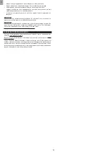
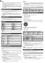
To pair the sensor, tap
on the homepage, then select
Sensor pairing
.
Follow the screen instructions to finish the pairing steps.
OR
3
Содержание WMR500A
Страница 1: ...USER MANUAL Professional all in one Weather Station Model WMR500A...
Страница 2: ...EN 1 FR 7 ES 13...
Страница 21: ...2018 Oregon Scienti c All rights reserved...

