EN
4
THGn132n
1
2
3
4
5
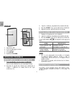
1. LED status indicator
2. Wall mount hole
3. Battery compartment
4.
ReSeT
hole
5.
CHAnneL
switch
GeTTInG STARTeD
ReMOTe SenSOR InSTALLATIOn
1. Step applicable only to THGR122N:
Using a Philips screwdriver, open the battery
compartment cover.
2. Slide channel switch to select channel 1. Ensure
you use a different channel for the other sensors
(2, 3).
3. Insert the batteries, matching the polarities.
4. Press
ReSeT
after each battery change.
5. Replace the battery compartment cover.
MAIn UnIT InSTALLATIOn
1. Remove the battery compartment.
2. Insert the batteries, matching the polarities.
3. Press
ReSeT
after each battery change.
The battery icon
may appear in the following
areas:
AReA
MeAnInG
Main unit
environment area
Main unit batteries low
Remote sensor
environment area
Remote sensor batteries
low
nOTe
•
We recommend that you use alkaline batteries with
this product for longer usage and lithium batteries in
temperatures below freezing.
•
Batteries should not be exposed to excessive heat
such as sunshine or fire.
Содержание RAR502S
Страница 81: ...1 LCD RAR502S 2 2 2 3 3 4 4 4 5 5 6 6 6 6 7 7 7 8 Oregon Scientific 9...
Страница 82: ...2 6 5 4 3 2 1 1 2 3 4 5 6 1 4 5 2 3 1 2 3 4 C F 5...
Страница 83: ...3 1 1 AC 3 3 THGR122N 2 1 3 4 5 6 1 2 LED 3 4 5 6...
Страница 84: ...4 THGN132N 1 2 3 4 5 1 LED 2 3 4 5 1 THGR122N 2 1 2 3 3 4 5 1 2 3...
Страница 85: ...5 AC DC 30 30 98 1 2 3...
Страница 86: ...6 3 30 50 19 31 12 24 C F C F 60 60...
Страница 90: ...1 LCD RAR502S 2 2 2 3 3 4 4 4 5 5 6 6 6 6 6 7 7 8 Oregon Scientific 9...
Страница 91: ...2 6 5 4 3 2 1 1 2 3 4 5 6 1 4 5 2 3 1 2 3 4 C F 5...
Страница 92: ...3 1 1 AC 3 3 THGR122N 2 1 3 4 5 6 1 2 LED 3 4 5 6...
Страница 93: ...4 THGN132N 1 2 3 4 5 1 LED 2 3 4 5 1 THGR122N 2 1 2 3 3 4 5 1 2 3...
Страница 94: ...5 AC DC 30 30 98 1 2 3...
Страница 95: ...6 3 30 50 19 31 12 24 C F C F 60 60 LL L LL HH H HH...


