


18
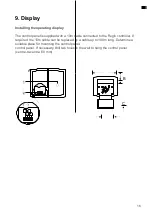
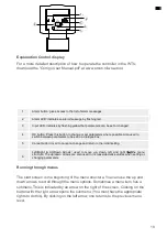
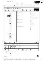
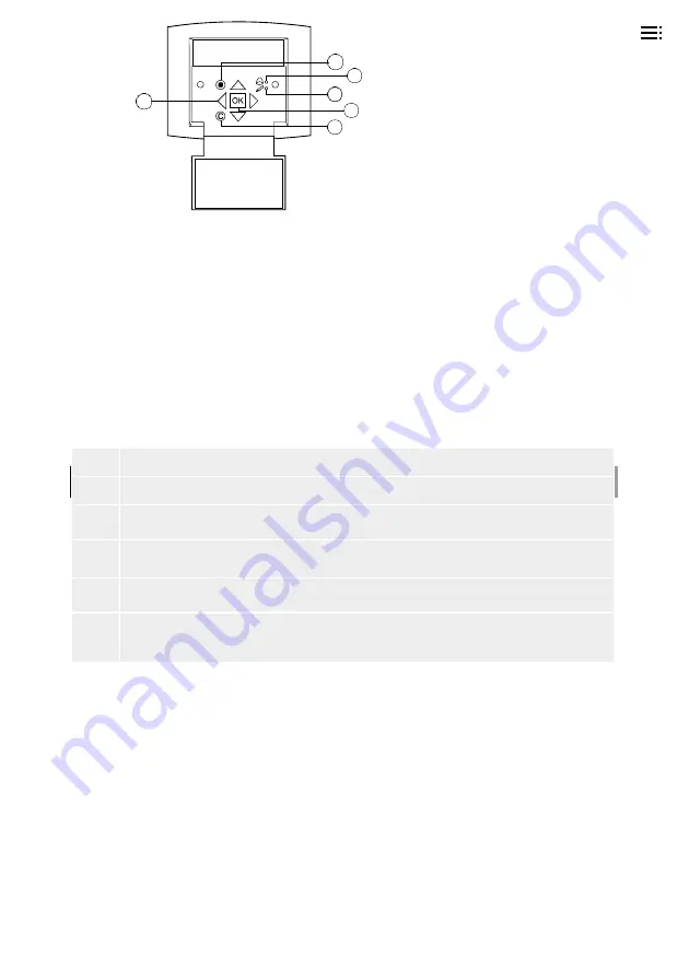
Explanation Control display
For a more detailed description of how to operate the controller in the WTU,
download the "Corrigo User Manual.pdf" at www.orcon.nl/wtu-etool.
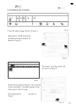
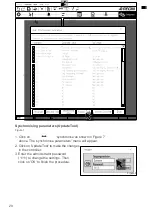
Running through menus
The start screen is the beginning of the menu structure. You can use the up and
down arrows to scroll through the menu options. Sometimes a menu item has a
submenu. This is indicated by an arrow on the right of the screen. Clicking on the
button with the right arrow opens the submenu. (You must have the appropriate
rights to do this). By clicking on the left arrow, one returns to the previous menu
level.
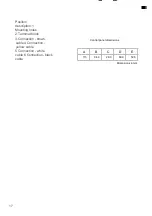
Posit
ion
Statement
1
Alarm button: gives access to the list of alarm messages
2
Alarm LED: indicates an alarm message by flashing red.
3
Input LED: indicates by flashing yellow that parameters can be set or changed.
4
OK button: Press this button to change or set parameters where possible. Also used to
switch between parameters to be set in a dialogue box.
5
Cancel button: Used to cancel a change and return to the initial setting.
6
Left/Right & Up/Down Arrows: used to move up, down, left and right through the menu
structure. The up/down arrows are also used to increase/decrease values when setting or
changing parameters.
1
2
6
3
4
5
Содержание WTU-1000-EC-E
Страница 2: ...2...
Страница 6: ...6 carried out...
Страница 16: ...16 Note The connections shown in a box are optional Electrical Connections WTU EC E IE TA...
Страница 41: ...40 Notes...


