4
Fitting and maintenance instructions HRC 300/400 4B(P/RH)
3. Installation
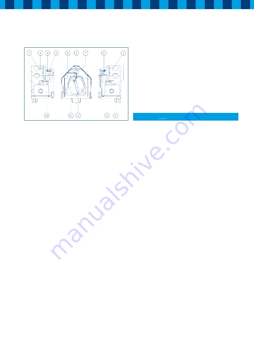
1.
Temperature sensor (4x)
Measures the temperatures in all connected ducts
2.
Humidity sensor
Measures the relative humidity in the exhaust air
3.
Central PCB ( 3.1)
This pcb controls the fans, sensors and decides which
function is activated
4.
Dip switches
Used to adjust the airflow for each speed setting
5.
Filters
Both supply and extract air is filtered
6.
Left/Right module
For left or right-handed orientation (house-tree / tree-house)
7.
Display Panel
Displays the current status and any failure of the HRC
8.
Receiver PCB (only RH)
Pcb for wireless remote controlled HRC
9.
Condensate-trap
Connection for condensate drain with water trap
10. Fan Right
Constant Flow fan with brushless EC motor supplies fresh
filtered air to the dwelling or extracts stale air from the
building depending on selected orientation of the HRC
11.
Bypass valve
For supply of cool outside air in the summer
12.
Heat exchanger
Takes care of the heat exchange between both airflows
13. Ventilator module left
Constant Flow fan with brushless EC motor supplies fresh
filtered air to or extracts stale air from the dwelling depending
on selected orientation of the HRC.
3.1 Mounting frame
The mounting frame of the HRC can be fitted directly to the wall
with the delivered screws and plugs. The distance between both
mounting-holes will be 53 cm. Under the mounting frame
ensure there is at least 50 cm for the condensate discharge
to be connected. On the mounting frame is a drawing, which
indicates where to fit the condensate discharge. The position
of the electrical power supply (an earthed wall socket or fused
switched spur) is also indicated. The unit must be secured
horizontally. Ensure sufficient angle for the condensate
discharge. The installation must be in a frost-free room.
Make sure there is a free space of at least 80 cm at the front of the
appliance for cleaning the filter and carrying out maintenance
on the appliance.
3.2 Important instruction
The HRC unit must be installed in accordance with all relevant
Building Regulations and Health & Safety requirements and the
fitting instructions of the HRC 300/400 4B(P/RH)
Connect mains
after
mounting the ducts!
3.3 Connecting ducts
When the mounting frame is fitted, the ducts can be fitted.
On one side of the unit the duct to and from the dwelling, on
the other side the ducts from and to outside.
To prevent condensation on the outside of the exterior air,
the inlet duct and the air outlet duct from the HRC must be
insulated.
It is recommended that the ducts from and to the dwelling
and to the appliance use flexible ducting with a minimum
length of 150 cm and flexible connections of the ducts to and
from the outside to the appliance use flexible ducting with
a minimum length of 50 cm. Flexible ducting should be fully
extended but should not place any strain on the terminal or
fixings.
Remember when sizing the ducts that this part of the installation
will affect energy efficiency. So remember that energy will be
wasted, during the passage of the air through the ductwork,
if the ducts are too small. If possible ensure that the total
resistance of the inlet- as well as the exhaustsystem does not
exceed 100 Pascal.
Figure 1: Parts of heat recovery module HRC 300/400 4B(P/RH)


