3
Fitting and maintenance instructions HRC 300/400 4B(P/RH)
2.1 General
The Orcon HRC is a complete heat recovery unit, which is
fitted with an intelligent electronic control system to ensure
optimum efficiency and protection under all conditions.
The unit can easily be set up for left- or a right-handed opera-
tion. By changing the position of a module at the top of the
unit it can quickly be configured to accomodate the ducting
to outside on either the left or on the right side of the unit.
With the screws and plugs supplied fit the unit horizontally
to the wall. A standard the unit is delivered complete with a wall
mounting frame, fitting instructions, fixing kit and a condensate
discharge trap. A wireless remote control is an optional extra.
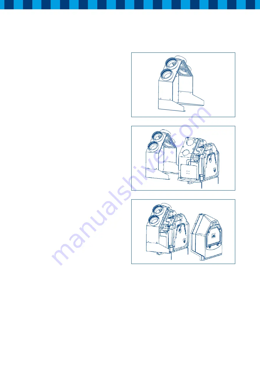
2.2 Fitting HRC in brief
A
Mounting frame: Mounted by means of the screws and plugs
supplied horizontally to the wall. Use the fixing points on
the drawing attached to the mounting frame. When the frame
is mounted horizontally to the wall, the ducting runs can be
completed. Remember that both ducts to and from outside,
will be fitted to one side of the unit and the ducts to and from
the house are attached to the other side of the unit. Also
the condensate discharge under the unit can be fitted at
this stage.
B
When the ducting runs are completed if an appropriate
electrical supply is present, the installation can be com-
pleted. Now the heat recovery module can be attached to
the frame. Ensure that the “tree” on the left/right module
corresponds to the side of the unit with the ducts to and
from outside and the “house” is on the internal side. On
the central PCB (3.1) adjust the air volume of the fans for
low, middle and high speed. Both fans are adjusted to the
same airflow to guarantee a balanced airflow. Push the heat
recovery module fully to the back of the mounting frame
and turn the handles at the bottom 180° to lock the unit
in place. Also the condensation trap under the unit can be
securely fastened with the wire clip supplied.
C
The cover of the unit can now be replaced and secured with
the two screws and the power-supply can be connected. The
unit will start-up immediately and begin to run but must be
calibrated as described on page 13 in the start-up-procedure.
When there are no failures during the start-up, the unit is
ready and fully commissioned.
For further information about the operation, adjustment, failures
and maintenance of the unit, read the next pages carefully.
2. Version
A
B
C


