MNL940-003-000-
7
2.0
THEORY OF OPERATION
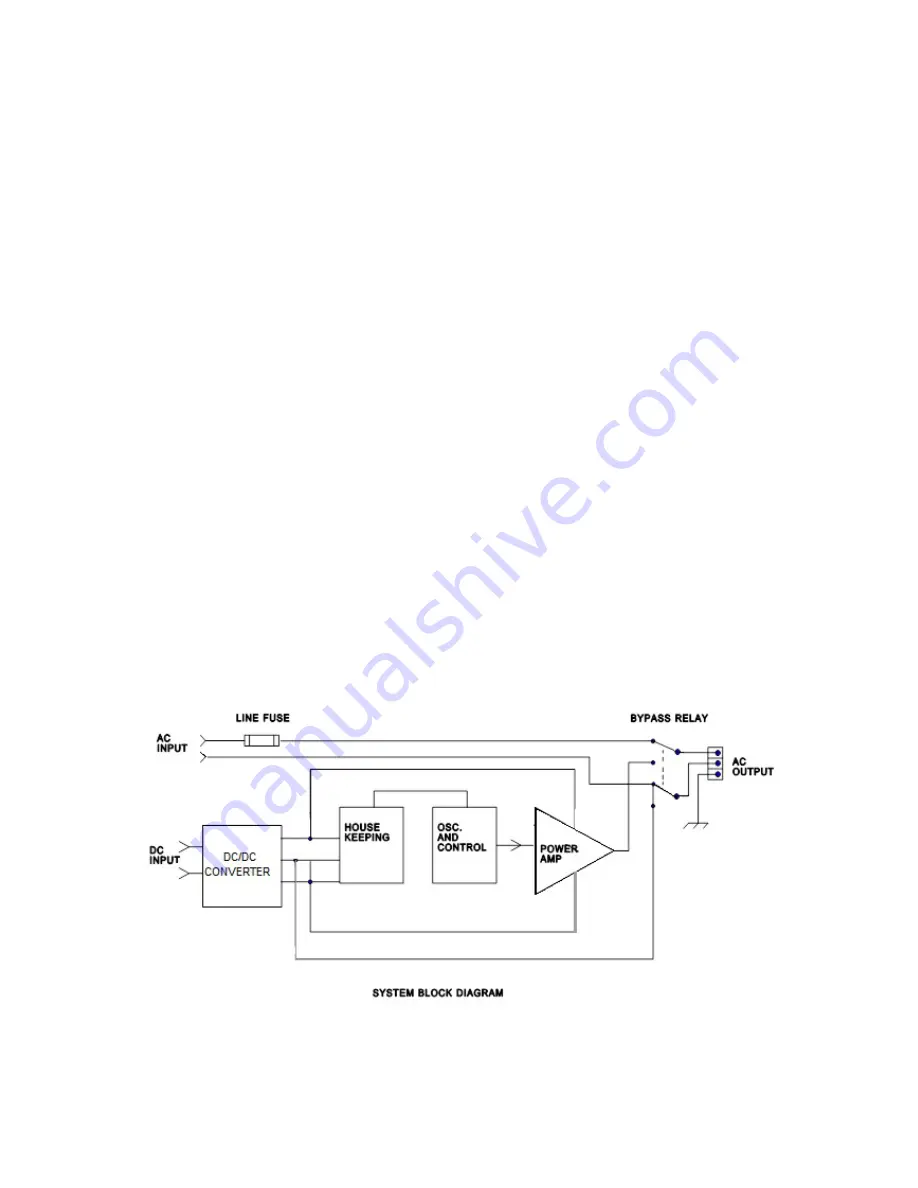
The INV 1210 series utilizes high frequency switched mode power conversion to
convert the incoming DC to an AC output. The first stage is a DC to DC converter which
“steps - up” the input voltage to a reg/- 160 Vdc. This voltage is applied to a
second high frequency “house keeping” supply and the output inverter. The house-
keeping supply provides operating voltage for the output inverter and alarm circuits.
The output section consists of a crystal controlled oscillator and power switching
devices. The crystal derived clock frequency is divided down and applied to optically
isolated IGBT drivers. The result is a 320V p/p pulse train at the output Frequency. The
peak value of this pulse train is equivalent to the peak value of a 120Vac rms. This type
of waveform is known as Modified sinewave.
The control circuitry on the output inverter assembly also provides protective functions.
Output current is measured and used to provide foldback type limiting in the event of an
overload. Output short circuits will terminate output pulses, when peak current exceeds
approximately 60 Amperes. If the overload is left unattended the unit will enter a “burst
mode” as it repeatedly attempts to drive the overload.
The alarm and bypass circuits ( if provided ) allow for external monitoring of input
and output status. The AC input/ bypass feature allows the AC power line to be applied
to the model INV 1210 and sent directly to the output terminals. In the event the AC
is interrupted, a relay will switch the output to the inverter. Units supplied with the D1
option will switch the line through when the DC is not available or the inverter has
a fault .The AC input is fused at 15 amps.


