background image

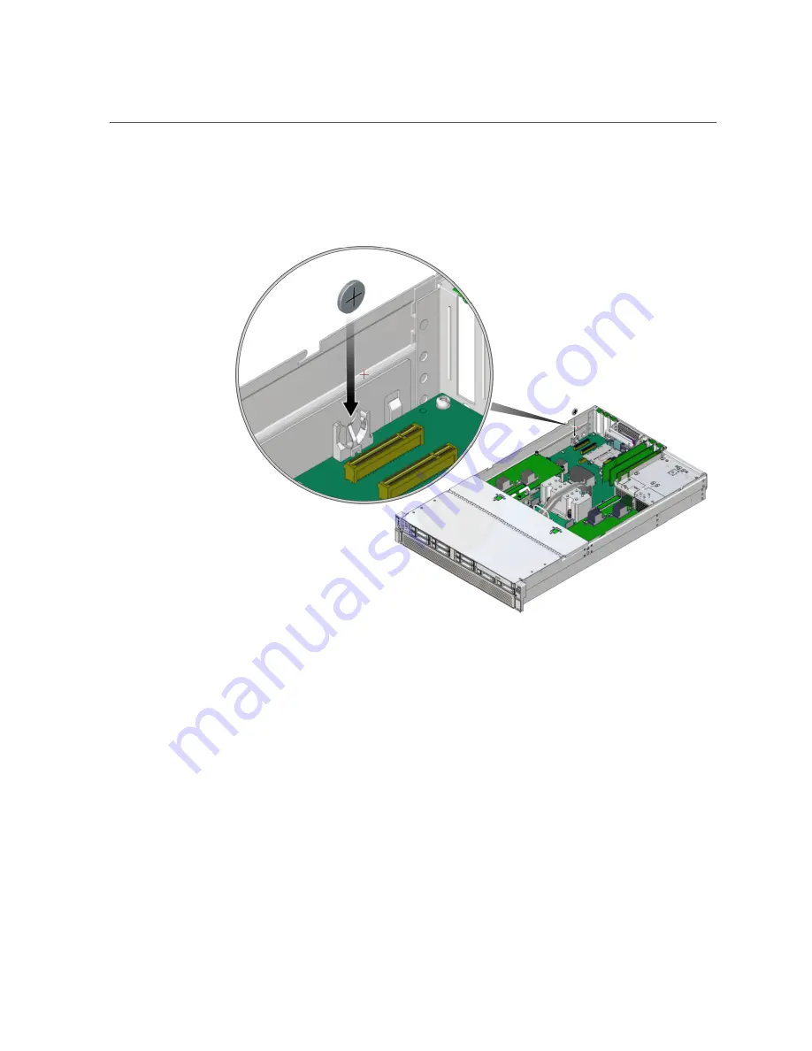
Replace the Battery

Press the new battery into the battery holder with the positive side (+) facing away from

the metal tab that holds it in place.

e.   

If you needed to remove a PCIe card from slot 6, replace that card.

See 

“Install a PCIe Card or Filler” on page 117

.

f.   

Return the Server to Operation

.

3.

Reset the system clock.

a.   

Use the Oracle ILOM 

clock

 command to reset the system clock.

The following example sets the date to August 22, 2016, and the timezone to EDT.

-> 

set /SP/clock datetime=081221302016timezone=EDT

Set 'datetime' to '081221302016'
set 'timezone' to 'EDT'

128

SPARC T7-1 Server Service Manual • May 2017

Содержание SPARC T7-1

Страница 1: ...SPARC T7 1 Server Service Manual Part No E54980 06 May 2017 ...

Страница 2: ......

Страница 3: ...rmation management applications It is not developed or intended for use in any inherently dangerous applications including applications that may create a risk of personal injury If you use this software or hardware in dangerous applications then you shall be responsible to take all appropriate fail safe backup redundancy and other measures to ensure its safe use Oracle Corporation and its affiliat...

Страница 4: ...n des informations Ce logiciel ou matériel n est pas conçu ni n est destiné à être utilisé dans des applications à risque notamment dans des applications pouvant causer un risque de dommages corporels Si vous utilisez ce logiciel ou ce matériel dans le cadre d applications dangereuses il est de votre responsabilité de prendre toutes les mesures de secours de sauvegarde de redondance et autres mesu...

Страница 5: ...s 23 Log In to Oracle ILOM Service 24 Identify Faulted Components 24 Identify Disabled Components 26 Component Names Displayed by Diagnostic Software 27 Interpreting LEDs 29 Front Panel Controls and LEDs 30 Rear Panel Controls and LEDs 32 Performing Advanced Troubleshooting 34 Check the Message Buffer 34 View Log Files Oracle Solaris 35 View Log Files Oracle ILOM 35 POST Overview 36 Configure POST...

Страница 6: ...er Off the Server Emergency Shutdown 49 Disconnect Power Cords 49 Accessing Server Components 50 Prevent ESD Damage 50 Extend the Server to the Service Position 51 Release the CMA 52 Remove the Server From the Rack 54 Remove the Top Cover 55 Open and Remove the Airflow Cover 56 Remove the Fan Cover 57 Attachment of Devices During Service 59 Servicing Drives 61 Drive LEDs 62 Determine Which Drive I...

Страница 7: ...ory to the Server 93 Locating and Replacing a Faulty DIMM 94 Locate a Faulty DIMM Oracle ILOM 94 Locate a Faulty DIMM LEDs 95 Replace a Faulty DIMM 96 Remove a Memory Riser 97 Remove a DIMM or DIMM Filler 101 Install a DIMM or DIMM Filler 102 Install a Memory Riser 105 Enable and Verify a DIMM 109 DIMM Configuration Errors 111 Servicing PCIe Cards 113 PCIe Card Configuration 113 I O Root Complex C...

Страница 8: ...154 Reactivate RAID Volumes 161 Verify the Motherboard 164 Servicing the Drive Backplane 165 Remove the Drive Backplane 165 Install the Drive Backplane 168 Verify the Drive Backplane 171 Returning the Server to Operation 173 Replace the Fan Cover 173 Install and Close the Airflow Cover 175 Replace the Top Cover 178 Return the Server to the Normal Operating Position 179 Attach Power Cords 180 Power...

Страница 9: ...Contents Index 187 9 ...

Страница 10: ...10 SPARC T7 1 Server Service Manual May 2017 ...

Страница 11: ... providers Required knowledge Advanced experience troubleshooting and replacing hardware Product Documentation Library Documentation and resources for this product and related products are available at http www oracle com goto t7 1 docs Feedback Provide feedback about this documentation at http www oracle com goto docfeedback Using This Documentation 11 ...

Страница 12: ...12 SPARC T7 1 Server Service Manual May 2017 ...

Страница 13: ...ions on page 16 Server Block Diagram on page 19 Related Information Detecting and Managing Faults on page 23 Preparing for Service on page 41 Front Panel Components Service The following figure shows the layout of the server front panel including the power and server locator buttons and the various status and fault LEDs Note The front panel also provides access to internal drives the removable med...

Страница 14: ...on page 30 Servicing the SPM on page 131 6 Serial number Find the Server Serial Number on page 44 7 HDD 0 Servicing Drives on page 61 8 HDD 1 Servicing Drives on page 61 9 HDD 2 or NVMe 0 Servicing Drives on page 61 10 HDD 3 or NVMe 1 Servicing Drives on page 61 11 HDD 4 or NVMe 2 Servicing Drives on page 61 12 HDD 5 or NVMe 3 Servicing Drives on page 61 13 HDD 6 Servicing Drives on page 61 14 HDD...

Страница 15: ...r Panel Components Service on page 15 Internal Component Locations on page 16 Server Block Diagram on page 19 Rear Panel Components Service No Description Links 1 Power supply 0 status indicator LEDs Servicing Power Supplies on page 83 2 Power supply 1 status indicator LEDs Servicing Power Supplies on page 83 3 PCIe card slot 1 Servicing PCIe Cards on page 113 4 PCIe card slot 2 Servicing PCIe Car...

Страница 16: ...age 113 12 PCIe card slot 5 Servicing PCIe Cards on page 113 13 PCIe card slot 6 Servicing PCIe Cards on page 113 Related Information Front Panel Components Service on page 13 Internal Component Locations on page 16 Server Block Diagram on page 19 Internal Component Locations The following figure identifies the replaceable component locations with the top cover removed Note The two memory risers a...

Страница 17: ...or SYS DBP NVME1 SYS DBP HDD4 or SYS DBP NVME2 SYS DBP HDD5 or SYS DBP NVME3 SYS DBP HDD6 SYS DBP HDD7 right Servicing Drives on page 61 2 DVD drive SYS MB DBP DVD Servicing the DVD Drive on page 139 3 Drive backplane on drive cage SYS DBP Servicing the Drive Backplane on page 165 4 Fan module cover Remove the Fan Cover on page 57 Identifying Components 17 ...

Страница 18: ...risers SYS MB CM CMP MR0 SYS MB CM CMP MR1 Servicing Memory Risers and DIMMs on page 89 10 DIMMs on motherboard SYS MB CM CMP BOB 0 3 CH 0 1 DIMM0 Servicing Memory Risers and DIMMs on page 89 11 Battery SYS MB BAT Servicing the Battery on page 125 12 PCIe cards SYS MB PCIE1 SYS MB PCIE2 SYS MB PCIE3 SYS MB PCIE4 SYS MB PCIE5 SYS MB PCIE6 Servicing PCIe Cards on page 113 13 SPM SYS MB SPM Servicing...

Страница 19: ...r Block Diagram on page 19 Server Block Diagram This block diagram shows the connections between and among components and device slots on the server Use this diagram to determine the optimum locations for optional cards or other peripherals based on your server s configuration and intended use Note For more detail on root complexes related to the PCIe slots see I O Root Complex Connections on page...

Страница 20: ...Server Block Diagram This table identifies some key path names in this server 20 SPARC T7 1 Server Service Manual May 2017 ...

Страница 21: ...1 HDD 3 NVMe 1 pci 301 pci 2 scsi 0 disk p3 pci 303 pci 1 pci 0 pci 7 nvme 0 disk 1 HDD 4 NVMe 2 pci 301 pci 2 scsi 0 disk p4 pci 303 pci 1 pci 0 pci 4 nvme 0 disk 1 HDD 5 NVMe 3 pci 301 pci 2 scsi 0 disk p4 pci 303 pci 1 pci 0 pci 5 nvme 0 disk 1 HDD 6 pci 301 pci 2 scsi 0 disk p6 HDD 7 pci 301 pci 2 scsi 0 disk p7 DVD pci 300 pci 2 usb 0 hub 8 device 1 storage 0 disk 0 Related Information Compon...

Страница 22: ...22 SPARC T7 1 Server Service Manual May 2017 ...

Страница 23: ...rpreting LEDs on page 29 2 Perform additional troubleshooting if needed Performing Advanced Troubleshooting on page 34 3 Manage faults following a service procedure Clear a Fault Manually on page 39 4 Contact technical support if the problem persists https support oracle com Related Information Identifying Components on page 13 Preparing for Service on page 41 Returning the Server to Operation on ...

Страница 24: ...preting LEDs on page 29 Performing Advanced Troubleshooting on page 34 Clear a Fault Manually on page 39 Log In to Oracle ILOM Service At the terminal prompt type ssh root SP IP address Password password Oracle R Integrated Lights Out Manager Version 3 2 x Copyright c 2014 Oracle and or its affiliates Inc All rights reserved Related Information Identify Faulted Components on page 24 Identify Disab...

Страница 25: ... 1 0 System Manufacturer Oracle Corporation Name SPARC T7 1 Part_Number 12345678 11 1 Serial_Number 1238BDC0DF Suspect 1 of 1 Fault class fault component misconfigured Certainty 100 Affects SYS MB CM CMP BOB21 CH1 DIMM Status faulted FRU Status faulty Location SYS MB CM CMP BOB21 CH1 DIMM Manufacturer Hynix Semiconductor Inc Name 8192MB DDR4 SDRAM DIMM Part_Number 70xx001 HMA4xxR7MFRxx TFT7 Revisi...

Страница 26: ...re information about this type of fault a Obtain the message ID from console output SPT 8000 PX in the example above b Go to https support oracle com and search on the message ID in the Knowledge tab or type the URL from the Action field into a browser 3 Follow the suggested actions to repair the fault 4 If necessary clear the fault manually See Clear a Fault Manually on page 39 Related Informatio...

Страница 27: ..._config_state Enabled SYS MB CM CMP BOB21 CH1 DIMM current_config_state Enabled SYS MB CM CMP BOB21 CH1 DIMM disable_reason Configuration Rules SYS MB CM CMP BOB21 CH1 DIMM fru_name 8192MB DDR4 SDRAM DIMM Related Information Log In to Oracle ILOM Service on page 24 Identify Faulted Components on page 24 Component Names Displayed by Diagnostic Software on page 27 Component Names Displayed by Diagno...

Страница 28: ...g Drives on page 61 DVD drive SYS MB DBP DVD Servicing the DVD Drive on page 139 eUSB drive SYS MB EUSB_DISK Fan modules As viewed from front of server SYS MB FM0 left SYS MB FM1 SYS MB FM2 SYS MB FM3 right Servicing Fan Modules on page 73 Memory risers SYS MB CM CMP MR0 SYS MB CM CMP MR1 Servicing Memory Risers and DIMMs on page 89 Motherboard SYS MB Servicing the Motherboard on page 147 PCIe car...

Страница 29: ...on page 30 Rear Panel Controls and LEDs on page 32 2 Check the LEDs on the individual components Component LEDs might not be lit even though the component is faulty Rely on software to determine if a component is faulty see Identify Faulted Components on page 24 Servicing Drives on page 61 Servicing Fan Modules on page 73 Servicing Power Supplies on page 83 Servicing Memory Risers and DIMMs on pag...

Страница 30: ...t conditions individual component fault LEDs are lit in addition to the Service Required LED 3 Power OK LED green Indicates these conditions Off Server is not running in its normal state Server power might be off The SP might be running Steady on Server is powered on and is running in its normal operating state No service actions are required Fast blink Server is running in standby mode and can be...

Страница 31: ...cknowledged and a service action is required on at least one of the fan modules 7 Server Power Supply Fault LED amber PS Indicates these conditions Off Steady state no service action is required Steady on A fault has been detected on one of the two power supplies 8 Server Overtemp LED amber Indicates these conditions Off Steady state no service action is required Steady on A temperature failure ev...

Страница 32: ... no service action is required Steady on A fault has been detected on this power supply 2 PS DC OK LED green Indicates these conditions Off 12V DC output from this power supply is disabled or not within specification Steady on 12V DC output from this power supply is present and within specifications 32 SPARC T7 1 Server Service Manual May 2017 ...

Страница 33: ...Server is running in standby mode and can be quickly returned to full function Slow blink A normal but transitory activity is taking place Slow blinking might indicate that system diagnostics are running or that the system is booting 6 Host Ethernet Port Link Activity LED green From left to right NET 1 NET 0 NET 3 and NET 2 Indicates these conditions Off No link is established Steady On A link is ...

Страница 34: ...Solaris on page 35 View Log Files Oracle ILOM on page 35 Generate and examine low level diagnostic information generated by POST POST Overview on page 36 Configure POST on page 36 Oracle ILOM Properties That Affect POST Behavior on page 38 Related Information Checking for Faults on page 23 Interpreting LEDs on page 29 Clear a Fault Manually on page 39 Check the Message Buffer The dmesg command che...

Страница 35: ... file After a period of time usually every week a new messages file is automatically created The original contents of the messages file are rotated to a file named messages 1 Over a period of time the messages are further rotated to messages 2 and messages 3 and then deleted 1 Log in as superuser 2 Type more var adm messages 3 To view all logged messages type more var adm messages Related Informat...

Страница 36: ...PARC host keyswitch state in the Oracle ILOM Administrator s Guide for Configuration and Maintenance Firmware Release 3 2 x for a list of parameters and values If POST detects a faulty component the component is disabled automatically If the server is able to run without the disabled component the server boots when POST completes its tests For example if POST detects a faulty processor core the co...

Страница 37: ...n running after an error reset error_level Possible values off min max error_level User role required for set r error_verbosity Diag verbosity when running after an error reset error_verbosity Possible values none min normal max error_verbosity User role required for set r hw_change_level Diag level when running after a hw change hw_change_level Possible values off min max hw_change_level User rol...

Страница 38: ...s For example show HOST diag HOST diag Targets Properties default_level off default_verbosity normal error_level max error_verbosity normal hw_change_level max hw_change_verbosity normal Commands cd set show Related Information POST Overview on page 36 Oracle ILOM Properties That Affect POST Behavior on page 38 Oracle ILOM Properties That Affect POST Behavior There are a number of Oracle ILOM comm...

Страница 39: ... that component has cleared Use the fmadm faulty command to confirm that the fault is clear 2 Determine your next step If no fault was detected you do not need to do anything else Do not perform the subsequent steps If a fault was detected continue to the next step 3 Clear the fault from all persistent fault records In some cases even though the fault is cleared some persistent fault information r...

Страница 40: ...ar that fault in the Oracle Enterprise Manager Ops Center software You must manually clear the fault or incident For more information refer to the section on marking an incident repaired in the Oracle Enterprise Manager Ops Center Feature Reference Guide at http www oracle com pls topic lookup ctx oc122 6 If you are servicing a component return to the procedure for that component Related Informati...

Страница 41: ...m the server Removing Power From the Server on page 46 8 Move the server out of the rack and remove covers as necessary to gain access to internal components Accessing Server Components on page 50 9 Attach devices to the server to perform service procedures Attachment of Devices During Service on page 59 Related Information Identifying Components on page 13 Returning the Server to Operation on pag...

Страница 42: ... devices such as the cards drives and DIMMS require special handling Caution Circuit boards and drives contain electronic components that are extremely sensitive to static electricity Ordinary amounts of static electricity from clothing or the work environment can destroy the components located on these boards Do not touch the components along their connector edges Caution You must disconnect all ...

Страница 43: ...wing tools for most service operations Antistatic wrist strap Antistatic mat No 2 Phillips screwdriver No 1 flat blade screwdriver battery removal T6 Torx screwdriver T10 Torx screwdriver Related Information Safety Information on page 41 Prevent ESD Damage on page 50 Fillers A filler is an empty metal or plastic enclosure that is installed at the factory or in the field into a server component slo...

Страница 44: ...umber You need the serial number of the server s chassis to obtain technical support for the system Note When a drive backplane SPM or motherboard is replaced the chassis serial number and part number might need to be programmed into the new component This must be done in a special service mode by trained service personnel Locate the serial number using one of the following methods Read the serial...

Страница 45: ... set System locator_indicator off Related Information Front Panel Components Service on page 13 Component Service Categories The server components and assemblies that can be replaced in the field fall into three categories Hot service replaceable by customer Cold service replaceable by customer Cold service replaceable by authorized service personnel Cold service procedures require that you shut t...

Страница 46: ...s Servicing Memory Risers and DIMMs on page 89 PCIe cards Servicing PCIe Cards on page 113 Battery Servicing the Battery on page 125 SPM Servicing the SPM on page 131 SC PROM Servicing the Motherboard on page 147 eUSB Drive Cold service replaceable by authorized service personnel Motherboard Servicing the Motherboard on page 147 Transfer system configuration PROM to new motherboard Drive backplane...

Страница 47: ...erver 1 Log in as superuser or equivalent Depending on the type of problem you might want to view server status or log files You also might want to run diagnostics before you shut down the server 2 Notify affected users that the server will be shut down Refer to the Oracle Solaris system administration documentation for additional information 3 Save any open files and quit all running programs Ref...

Страница 48: ...r on page 47 2 Switch from the system console to the Oracle ILOM prompt by typing the Hash Dot key sequence 3 Power off the server stop System Note You can also use the Server Power button on the front of the server to initiate a graceful server shutdown See Power Off the Server Server Power Button Graceful on page 48 Related Information Prepare to Power Off the Server on page 47 Power Off the Ser...

Страница 49: ...er Emergency Shutdown Caution All applications and files will be closed abruptly without saving changes File system corruption might occur 1 Prepare to power off the server See Prepare to Power Off the Server on page 47 2 Press and hold the Power button for five seconds Related Information Prepare to Power Off the Server on page 47 Power Off the Server Oracle ILOM on page 48 Power Off the Server S...

Страница 50: ...e and the inside of the server Perform these tasks in this order as needed Prevent ESD Damage on page 50 Extend the Server to the Service Position on page 51 Release the CMA on page 52 Remove the Server From the Rack on page 54 Remove the Top Cover on page 55 Open and Remove the Airflow Cover on page 56 Remove the Fan Cover on page 57 Related Information Safety Information on page 41 Prevent ESD D...

Страница 51: ...y Information on page 41 Related Information Safety Information on page 41 Extend the Server to the Service Position You can service the following components with the server in the service position Drives or fillers DVD drive Power supplies Fans Memory risers DIMMs PCIe cards SPM eUSB drive Battery Note You can replace the drives and rear power supplies without extending the server into the servic...

Страница 52: ...ation Release the CMA on page 52 Remove the Server From the Rack on page 54 Release the CMA For some service procedures such as replacing a power supply if you are using a CMA you might need to release the CMA to gain access to the rear of the chassis Note For instructions on how to install the CMA for the first time refer to Prepare the CMA for Installation in SPARC T7 1 Server Installation Guide...

Страница 53: ...shed the service steps that require the CMA to be out of the way swing the CMA closed and latch it to the left rack rail Check that the CMA and the cables are functioning properly after completing service Related Information Extend the Server to the Service Position on page 51 Remove the Server From the Rack on page 54 Returning the Server to Operation on page 173 Preparing for Service 53 ...

Страница 54: ...nd the server to the maintenance position See Extend the Server to the Service Position on page 51 5 Release the CMA from the rail assembly The CMA is still attached to the cabinet but the server chassis is now disconnected from the CMA See Release the CMA on page 52 6 From the front of the server pull the release tabs forward and pull the server forward until it is free of the rack rails A releas...

Страница 55: ...M configurations will not be properly reflected in the service processor s inventory until you replace the top cover 1 Ensure that the AC power cords are disconnected from the server power supplies 2 Press the green button to release the top cover panel 1 3 Slide the cover towards the rear of the server chassis about 0 5 inch 12 mm 4 Lift up and remove the top cover panel 2 Related Information Rep...

Страница 56: ...ust open or remove the transparent airflow cover 1 Lift the edge of the airflow cover closest to the rear of the server The airflow cover can stand in its upright position Perform the next steps if you need to remove the airflow cover 2 Open the fan cover 56 SPARC T7 1 Server Service Manual May 2017 ...

Страница 57: ...he server Related Information Install and Close the Airflow Cover on page 175 Remove the Top Cover on page 55 Remove the Fan Cover on page 57 Remove the Fan Cover To access some components you must remove the fan cover 1 Remove 12 screws on the top and side of the fan cover Preparing for Service 57 ...

Страница 58: ...the Fan Cover Note The fan covers on some units are secured with T6 Torx screws Other units are secured with No 2 Phillips screws Illustration shows T6 Torx screws 58 SPARC T7 1 Server Service Manual May 2017 ...

Страница 59: ...e 173 Open and Remove the Airflow Cover on page 56 Remove the Top Cover on page 55 Attachment of Devices During Service During service procedures you might have to connect devices to the server For OS support connect an Ethernet cable to the one of the Ethernet connectors NET 0 NET 1 NET 2 or NET 3 Preparing for Service 59 ...

Страница 60: ...d NET MGT Note The SP uses the NET MGT out of band port by default You can configure the SP to share one of the sever s four Ethernet ports instead The SP uses only the configured Ethernet port If you plan to access the Oracle ILOM CLI through the management port connect a serial null modem cable to the RJ 45 serial port labeled SER MGT The USB connectors on the front panel support USB 2 0 The USB...

Страница 61: ...ash SSDs which are diskless storage devices based on solid state memory The server also can support NVMe drives in four of the drive bays Either type of drive can be a boot device The term drive is used in a generic sense to refer to both types of internal storage devices These topics explain how to service drives Drive LEDs on page 62 Determine Which Drive Is Faulty on page 63 Remove a Drive or D...

Страница 62: ...idle and available for use 3 OK Activity SSDs Green Indicates the drive s availability for use On Read or write activity is in progress Off Drive is idle and available for use Flashes on and off This situation occurs during hot service operations You can ignore this situation Note The front and rear panel Service Required LEDs are also lit when the server detects a drive fault See Front Panel Comp...

Страница 63: ... If you are unable to identify the faulty drive seek further information See Detecting and Managing Faults on page 23 4 Remove the faulty drive See Remove a Drive or Drive Filler on page 63 Related Information Drive LEDs on page 62 Remove a Drive or Drive Filler on page 63 Install a Drive or Drive Filler on page 68 Verify a Drive on page 69 Detecting and Managing Faults on page 23 Remove a Drive o...

Страница 64: ...the device tree including drives that are not configured cfgadm al This command lists dynamically reconfigurable hardware resources and shows their operational status In this case look for the status of the drive you plan to remove This information is listed in the Occupant column Ap_id Type Receptacle Occupant Condition c0 scsi bus connected configured unknown c0 dsk c1t0d0 disk connected configu...

Страница 65: ...drive s state has changed from POWERED to PRESENT hotplug list lc In this state the blue OK to Remove LED on the NVMe drive is lit Note Do not remove the drive unless the blue OK to Remove LED is lit 4 Determine whether you can replace the drive using the hot service procedure or whether you need to power off the server using the cold service procedure The cold service procedure is required if the...

Страница 66: ...from accessing it 6 If you are hot servicing the drive locate the drive that displays the amber Fault LED and ensure that the blue Ready to Remove LED is lit 7 Attach an antistatic wrist strap 8 On the drive or drive filler you want to remove complete the following tasks Caution The latch is not an ejector Do not bend it too far to the right Doing so can damage the latch a Push the release button ...

Страница 67: ...ve Otherwise the server might overheat due to improper airflow 9 After you remove an NVMe drive check that the drive slot s state has changed to EMPTY hotplug list lc 10 Install a replacement drive or a drive filler See Install a Drive or Drive Filler on page 68 Related Information Determine Which Drive Is Faulty on page 63 Install a Drive or Drive Filler on page 68 Verify a Drive on page 69 Servi...

Страница 68: ...the drive that was removed Drives are physically addressed according to the slot in which they are installed 1 Remove a drive or a drive filler See Remove a Drive or Drive Filler on page 63 2 Unpack the drive and place it on an antistatic mat 3 Fully open the release lever on the drive 4 Install the drive or drive filler by completing the following tasks a Slide the drive or drive filler into the ...

Страница 69: ...omatically power up and attach If not power up and attach the drive manually hotplug enable SYS DBP NVME0 Check that the drive s state has changed to ENABLED hotplug list lc 6 Verify the drive functionality See Verify a Drive on page 69 Related Information Determine Which Drive Is Faulty on page 63 Remove a Drive or Drive Filler on page 63 Verify a Drive on page 69 Verify a Drive Perform these ste...

Страница 70: ...your configuration 4 Verify that the blue Ready to Remove LED is no longer lit on the drive that you installed See Determine Which Drive Is Faulty on page 63 5 At the Oracle Solaris prompt list all drives in the device tree including any drives that are not configured cfgadm al The replacement drive is now listed as configured as shown in the following example Ap_Id Type Receptacle Occupant Condit...

Страница 71: ...sks are covered in the Oracle Solaris OS administration documentation For additional drive verification you can run Oracle VTS Refer to the Oracle VTS documentation for details Related Information Determine Which Drive Is Faulty on page 63 Remove a Drive or Drive Filler on page 63 Install a Drive or Drive Filler on page 68 Servicing Drives 71 ...

Страница 72: ...72 SPARC T7 1 Server Service Manual May 2017 ...

Страница 73: ...e server from the rack to access the fans Each fan module contains two fans mounted in an integrated hot serviceable component These topics describe how to service faulty fan modules Fan Module LEDs on page 74 Determine Which Fan Module Is Faulty on page 75 Remove a Fan Module on page 75 Install a Fan Module on page 78 Verify a Fan Module on page 81 Related Information Preparing for Service on pag...

Страница 74: ...Fan Module LEDs LED Color Status When Lit Power OK Green The server is powered on and the fan module is functioning correctly Service Required Amber The fan module is faulty 74 SPARC T7 1 Server Service Manual May 2017 ...

Страница 75: ...ult The Server Overtemp LED might also light if a fan fault causes an increase in server operating temperature Related Information Front Panel Components Service on page 13 Rear Panel Components Service on page 15 Extend the Server to the Service Position on page 51 Remove a Fan Module on page 75 Detecting and Managing Faults on page 23 Remove a Fan Module Caution While the fans provide some cooli...

Страница 76: ...rvicing a Attach an antistatic wrist strap See Prevent ESD Damage on page 50 b Extend the server to the maintenance position See Extend the Server to the Service Position on page 51 2 Open the fan door Slide the two green buttons to unlock the fan door then swing it open 3 Identify the faulty fan module with a corresponding Service Required LED 76 SPARC T7 1 Server Service Manual May 2017 ...

Страница 77: ...g a screw by hand use a No 2 Phillips screwdriver 5 Grasp the fan module and lift it out of the server Caution When removing a fan module do not rock it back and forth Rocking fans can damage the fan module connectors Caution When changing fan modules note that only the fan modules can be removed or replaced Do not service any other components in the fan compartment unless the server is shut down ...

Страница 78: ... on page 51 Install a Fan Module on page 78 Install a Fan Module Caution To ensure proper cooling ensure that you install the replacement fan module in the same slot from which the faulty fan was removed 1 Remove a fan module See Remove a Fan Module on page 75 2 Unpack the replacement fan module and place it on an antistatic mat 3 Open the fan door 78 SPARC T7 1 Server Service Manual May 2017 ...

Страница 79: ...Note Fan modules are keyed to ensure that they are installed in the correct orientation Ensure that the cables threaded between the two middle fan modules are not caught b Apply firm pressure to fully seat the fan module You will hear a click when the fan modue is properly seated c Tighten the green screw to hold the fan module in place panel 2 Servicing Fan Modules 79 ...

Страница 80: ... a Fan Module on page 81 6 Close the fan door Swing the fan door closed then press down until the two green buttons snap into place 7 Return the server to the normal operating position See Return the Server to the Normal Operating Position on page 179 8 When the server is powered verify the new fan module See Verify a Fan Module on page 81 80 SPARC T7 1 Server Service Manual May 2017 ...

Страница 81: ...e server can determine that the fan module is functioning properly 3 Use the Oracle ILOM show faulty command to verify that the fault has been cleared See Identify Faulted Components on page 24 for more information on using the show faulty command Consider these two possibilities If the previous steps did not clear the fault see Detecting and Managing Faults on page 23 for information about the to...

Страница 82: ...82 SPARC T7 1 Server Service Manual May 2017 ...

Страница 83: ...3 Remove a Power Supply on page 84 Install a Power Supply on page 85 Verify a Power Supply on page 87 Related Information Rear Panel Components Service on page 15 Locate a Faulty Power Supply View the following LEDs which are lit when a power supply fault is detected Rear PS Fault LED on the front bezel of the server See Front Panel Controls and LEDs on page 30 Service Required LED on the faulted ...

Страница 84: ...ow leave the failed power supply installed in the server until you replace it with a new power supply You can perform this procedure while the server is running See Component Service Categories on page 45 for more information about hot service procedures 1 Prepare for servicing a Attach an antistatic wrist strap b If necessary release the CMA to access the power supplies See Release the CMA on pag...

Страница 85: ...ent it from falling Caution Whenever you remove a power supply you should replace it with another power supply Otherwise the server might overheat due to improper airflow If a new power supply is not available leave the failed power supply installed until it can be replaced 5 Install a new power supply See Install a Power Supply on page 85 Related Information Locate a Faulty Power Supply on page 8...

Страница 86: ...upply chassis bay 4 Slide the power supply into the bay until it is fully seated You will hear an audible click when the power supply is fully seated 5 Reconnect the power cord to the power supply 6 If you disconnected the two CMA left side connectors reconnect the CMA For instructions on reconnecting the CMA see Attach the CMA to the Server in SPARC T7 1 Server Installation Guide 7 Verify that th...

Страница 87: ... Verify that the PS Fault LED on the front of the server is not lit 3 Use the Oracle ILOM show faulty command to verify that the fault has been cleared See Identify Faulted Components on page 24 for more information on using the show faulty command Consider these possibilities If the previous steps did not clear the fault see Detecting and Managing Faults on page 23 for information about the tools...

Страница 88: ...Verify a Power Supply Rear Panel Components Service on page 15 88 SPARC T7 1 Server Service Manual May 2017 ...

Страница 89: ...05 Enable and Verify a DIMM on page 109 DIMM Configuration Errors on page 111 Memory Riser and DIMM Configuration The motherboard provides eight slots for DIMMs You can add a pair of memory risers each with four DIMM slots making a total of 16 DIMMs in the server The memory configuration rules for the server are as follows In all configurations DIMMs must be identical same size same rank classific...

Страница 90: ...a DIMM or DIMM Filler on page 101 Install a DIMM or DIMM Filler on page 102 Checking DIMM Compatibility Each DIMM is affixed with an identifying label The first four characters on the label describe the DIMM memory capacity the second four characters describe the rank classification Use these labels to identify the DIMMs installed in the server to verify that any replacement DIMMs are compatible o...

Страница 91: ...4 Gbyte 8 Gbit Quad rank x8 4Rx4 Memory Riser and DIMM FRU Names The server can contain 16 DIMMs Eight DIMMs are installed on the motherboard An optional eight DIMMs can be installed on two memory risers mounted on the motherboard above the initial DIMMs Four DIMMs are installed on each memory riser Labels on the transparent airflow cover identify the naming of memory risers and DIMMs Servicing Me...

Страница 92: ... supplies is SYS MB CM CMP BOB21 CH0 Physical Location Seen From Rear Memory Riser or DIMM FRU Name Ejector Color Left Memory Riser 1 2 3 4 SYS MB CM CMP MR1 riser SYS MB CM CMP MR1 BOB00 CH0 SYS MB CM CMP MR1 BOB00 CH1 SYS MB CM CMP MR1 BOB10 CH0 SYS MB CM CMP MR1 BOB10 CH1 Black White Black White Left motherboard 5 6 SYS MB CM CMP BOB11 CH0 SYS MB CM CMP BOB11 CH1 Black White Black 92 SPARC T7 1...

Страница 93: ...lated Information Memory Riser and DIMM Configuration on page 89 Checking DIMM Compatibility on page 90 Locate a Faulty DIMM LEDs on page 95 Locate a Faulty DIMM Oracle ILOM on page 94 Enable and Verify a DIMM on page 109 Add Memory to the Server Caution These procedures require that you handle components that are sensitive to ESD Follow antistatic practices to avoid damage or component failure Cu...

Страница 94: ...ng DIMMs on the memory risers and the motherboard 7 Install the new DIMMs 8 Install the memory risers 9 Return the server to operation 10 Enable and verify the new DIMMs Locating and Replacing a Faulty DIMM You can locate a failed DIMM either by using the Oracle ILOM show faulty command or with the DIMM fault LEDs located on the motherboard and the memory risers After locating the faulty DIMM inst...

Страница 95: ... DIMM slot on the motherboard that is farthest from the power supplies Related Information Locate a Faulty DIMM LEDs on page 95 Checking DIMM Compatibility on page 90 Memory Riser and DIMM FRU Names on page 91 Remove a Memory Riser on page 97 Remove a DIMM or DIMM Filler on page 101 Locate a Faulty DIMM LEDs This procedure describes how to identify a faulty DIMM using buttons and LEDs on the mothe...

Страница 96: ...ation Locate a Faulty DIMM Oracle ILOM on page 94 Remove a Memory Riser on page 97 Remove a DIMM or DIMM Filler on page 101 Replace a Faulty DIMM Caution This procedure requires handling components that are sensitive to ESD Follow antistatic practices to avoid damage or component failure 96 SPARC T7 1 Server Service Manual May 2017 ...

Страница 97: ...M to enable access 5 Locate the faulty DIMM on the motherboard or memory riser using the DIMM fault LEDs 6 Remove the faulty DIMM 7 Ensure the replacement DIMM has the same rank classification as the faulty DIMM 8 Install the replacement DIMM 9 Install the memory riser that you removed 10 Return the server to operation 11 Enable and verify the replacement DIMM Remove a Memory Riser Caution These p...

Страница 98: ...pare for servicing a Attach an antistatic wrist strap b Power off the server and unplug the power cords c Extend the server to the service position d Remove the top cover 2 Loosen the four screws that attach the memory riser to the standoffs Use a No 2 Phillips screwdriver to loosen the captive screws 98 SPARC T7 1 Server Service Manual May 2017 ...

Страница 99: ...Remove a Memory Riser 3 Lift the handle on the memory riser to release it from the connector Servicing Memory Risers and DIMMs 99 ...

Страница 100: ...er on an antistatic mat 6 Install a new memory riser or continue with the service task that required removing the memory riser for access Related Information Remove a DIMM or DIMM Filler on page 101 Install a DIMM or DIMM Filler on page 102 Install a Memory Riser on page 105 100 SPARC T7 1 Server Service Manual May 2017 ...

Страница 101: ...ulty DIMMs When replacing a faulty motherboard You can perform this procedure but the server must first be completely powered down and all power cords unplugged See Component Service Categories on page 45 for more information about cold service procedures Caution Whenever you remove a DIMM or a DIMM filler you should replace it with another DIMM or DIMM filler before powering on the server Otherwi...

Страница 102: ...atic mat Related Information Install a DIMM or DIMM Filler on page 102 Remove a Memory Riser on page 97 Install a Memory Riser on page 105 Install a DIMM or DIMM Filler Caution This procedure requires handling components that are sensitive to ESD Follow antistatic practices to avoid damage or component failure 102 SPARC T7 1 Server Service Manual May 2017 ...

Страница 103: ... You can perform this procedure but the server must first be completely powered down and all power cords unplugged See Component Service Categories on page 45 for more information about cold service procedures Caution Whenever you remove a DIMM you should replace it with another DIMM before applying power to the server Otherwise the server might overheat due to improper airflow 1 Attach an antista...

Страница 104: ... ejector lever 3 Align each DIMM with the empty connector slot aligning the notch in the DIMM with the key in the connector The notch ensures that the DIMM is oriented correctly 4 Gently press the DIMM into the slot until the ejector tabs lock the DIMM in place Related Information Memory Riser and DIMM Configuration on page 89 104 SPARC T7 1 Server Service Manual May 2017 ...

Страница 105: ...ractices to avoid damage or component failure You can perform this procedure The system must be completely powered down before performing this procedure See Component Service Categories on page 45 for more information about cold service procedures Perform this procedure to install a memory riser in order to replace a faulty memory riser or to install a memory riser you removed to access other comp...

Страница 106: ...Install a Memory Riser The handle on the memory riser is closest to the center of the server 106 SPARC T7 1 Server Service Manual May 2017 ...

Страница 107: ...Install a Memory Riser 2 Lower the handle on the memory riser to seat the connector 3 Tighten the four screws that secure the memory riser to the standoffs Servicing Memory Risers and DIMMs 107 ...

Страница 108: ...See Install a DIMM or DIMM Filler on page 102 Related Information Memory Riser and DIMM Configuration on page 89 Checking DIMM Compatibility on page 90 Remove a Memory Riser on page 97 Remove a DIMM or DIMM Filler on page 101 Install a Memory Riser on page 105 Enable and Verify a DIMM on page 109 108 SPARC T7 1 Server Service Manual May 2017 ...

Страница 109: ...ult the set command will clear it set SYS MB CM CMP BOB21 CH0 requested_config_state Enabled 4 For a host detected fault perform the following steps to verify the new DIMM a Set the virtual keyswitch to diag so that POST runs in Service mode set HOST keyswitch_state Diag Set keyswitch_state to Diag b Power cycle the server stop System Are you sure you want to stop System y n y Stopping System star...

Страница 110: ...ty command fmadm faulty If any faults are reported refer to the diagnostics instructions described in Identify Faulted Components on page 24 5 Switch to the Oracle ILOM command shell 6 Type show faulty Target Property Value SP faultmgmt 0 fru SYS MB CM CMP BOB21 CH0 SP faultmgmt 0 timestamp Dec 14 22 43 59 SP faultmgmt 0 sunw msg id SUN4V 8000 DX faults 0 SP faultmgmt 0 uuid 3aa7c854 9667 e176 efe...

Страница 111: ... Memory Riser and DIMM Configuration on page 89 Any violations of these rules produce a general error message Please refer to the service documentation for supported memory configurations In some cases the server boots a degraded state WARNING Running with a nonstandard DIMM configuration Refer to service document for details In other cases the configuration error is fatal Fatal configuration erro...

Страница 112: ...112 SPARC T7 1 Server Service Manual May 2017 ...

Страница 113: ... 0 slots that accommodate low profile PCIe cards All slots support x8 PCIe cards and two slots can support x16 PCIe cards To determine the slot in which to install a PCIe card follow these guidelines 1 Install cards that require a specific slot Refer to the SPARC T7 1 Server Product Notes and the documentation for each card to determine if there are slot requirements The switch card supporting NVM...

Страница 114: ...PCIE2 3 0 3 0 pci 303 pci 1 SYS MB PCIE3 4 0 1 0 pci 302 pci 1 SYS MB PCIE4 5 0 1 1 pci 302 pci 2 SYS MB PCIE5 6 0 0 0 pci 301 pci 1 SYS MB PCIE6 Related Information Rear Panel Components Service on page 15 Server Block Diagram on page 19 PCIe Card Configuration on page 113 Remove a PCIe Card or Filler on page 114 Install a PCIe Card or Filler on page 117 Remove a PCIe Card or Filler Caution This ...

Страница 115: ... Extend the server to the maintenance position See Extend the Server to the Service Position on page 51 d Remove the top cover See Remove the Top Cover on page 55 2 Locate the PCIe card or filler that you want to remove See Rear Panel Components Service on page 15 for information about PCIe slots and their locations If you are removing a PCIe filler go to Step 6 3 Note the slot location for each P...

Страница 116: ...nism panel 1 b Carefully lift the PCIe card or filler from the card slot panel 2 7 Replace with another PCIe card or filler before the server is connected to power again See Install a PCIe Card or Filler on page 117 Related Information Install a PCIe Card or Filler on page 117 116 SPARC T7 1 Server Service Manual May 2017 ...

Страница 117: ...ace on an antistatic mat 3 Remove any transceivers from the PCIe card before installing the card 4 Ensure that the server is powered off and all power cords are disconnected from the server power supplies See Removing Power From the Server on page 46 5 Determine which slot to install the PCIe card in If you are not replacing an existing PCIe card and need information about deciding which slot to i...

Страница 118: ... 8 Return the server to operation a Install the top cover See Replace the Top Cover on page 178 b Return the server to the normal operating position See Return the Server to the Normal Operating Position on page 179 c Reconnect all power cords to the server power supplies See Attach Power Cords on page 180 d Power on the server 118 SPARC T7 1 Server Service Manual May 2017 ...

Страница 119: ...Ie card for information about configuring the PCIe card including installing required operating systems To create or recover RAID configurations refer to the LSI MegaRAID SAS Software User s Guide which is available at https www broadcom com support oem oracle Related Information PCIe Card Configuration on page 113 Remove a PCIe Card or Filler on page 114 Servicing PCIe Cards 119 ...

Страница 120: ...120 SPARC T7 1 Server Service Manual May 2017 ...

Страница 121: ... You can perform this cold service procedure Power down the server completely before performing this procedure Caution This procedure requires that you handle components that are sensitive to ESD This sensitivity can cause the components to fail To avoid damage ensure that you follow antistatic practices as described in Prevent ESD Damage on page 50 1 Prepare the system for service See Preparing f...

Страница 122: ...ith the new eUSB drive If the screw is too tight to remove by hand use a Torx 10 driver to loosen it 3 Lift the eUSB drive up to disconnect it from the motherboard 4 Install a new eUSB drive See Install the eUSB Drive on page 123 Related Information Install the eUSB Drive on page 123 122 SPARC T7 1 Server Service Manual May 2017 ...

Страница 123: ...handle components that are sensitive to ESD This sensitivity can cause the components to fail To avoid damage ensure that you follow antistatic practices as described in Prevent ESD Damage on page 50 1 Remove the eUSB drive See Remove the eUSB Drive on page 121 2 Ensure you are taking all ESD precautions before handling the eUSB drive See Prevent ESD Damage on page 50 Servicing the eUSB Drive 123 ...

Страница 124: ...d tighten the screw to secure the drive to the motherboard Do not use a tool to tighten the screw further 5 Return the server to operation See Returning the Server to Operation on page 173 Related Information Remove the eUSB Drive on page 121 124 SPARC T7 1 Server Service Manual May 2017 ...

Страница 125: ...efore performing these procedures Replace the Battery on page 125 Related Information Detecting and Managing Faults on page 23 Replace the Battery 1 Prepare the host for battery replacement To correctly reset the date and time before replacing a battery you must revent the host from automatically powering on and disable any NTP connections a Check the HOST_AUTO_POWER_ON property show SP policy HOS...

Страница 126: ...y Replacing the battery is a cold service procedure The server must be completely powered off and power cables disconnected before performing this procedure a Prepare the server for service b If a PCIe card is in slot 6 remove it to improve access to the battery See Remove a PCIe Card or Filler on page 114 c Remove the old battery 126 SPARC T7 1 Server Service Manual May 2017 ...

Страница 127: ...Replace the Battery Pinch the battery between two fingers and slide it up and out of the battery holder d Unpack and install the new battery Servicing the Battery 127 ...

Страница 128: ...ace that card See Install a PCIe Card or Filler on page 117 f Return the Server to Operation 3 Reset the system clock a Use the Oracle ILOM clock command to reset the system clock The following example sets the date to August 22 2016 and the timezone to EDT set SP clock datetime 081221302016timezone EDT Set datetime to 081221302016 set timezone to EDT 128 SPARC T7 1 Server Service Manual May 2017 ...

Страница 129: ... HOST_POWER_ON was enabled before you replaced the battery you must re enable it set SP policy HOST_POWER_ON enabled c If the SP clock usentpserver property was enabled before you replaced the battery you must re enable it set SP clock usentpserver enabled 4 Verify the battery show SYS MB BAT Related Information Identify Faulted Components on page 24 Servicing the Battery 129 ...

Страница 130: ...130 SPARC T7 1 Server Service Manual May 2017 ...

Страница 131: ...acing the SPM you must restore the configuration settings maintained in the SPM Before replacing the SPM save the configuration using the Oracle ILOM backup utility Refer to the Oracle ILOM documentation for instructions on backing up and restoring the Oracle ILOM configuration After replacing the SPM the new SPM firmware component and the existing host firmware component must be consistent with e...

Страница 132: ...ber SP OK Fault LED on the front panel will be lit when an SPM fault is detected 1 If possible back up the Oracle ILOM configuration before removing the SPM After you replace the SPM restoring the SPM configuration will be easier if you previously saved the configuration using the Oracle ILOM backup utility Refer to the Oracle ILOM documentation for instructions on backing up and restoring the Ora...

Страница 133: ...PM aside where it is protected from static You must reinstall the SPM on the new motherboard a Grasp the SPM by the two grasp points panel 2 and lift up to disengage the SPM from the connectors on the motherboard b Lift the SPM up and away from the motherboard panel 3 5 Install a new SPM See Install the SPM on page 134 Servicing the SPM 133 ...

Страница 134: ...ice procedure The server must be completely powered down before performing this procedure See Component Service Categories on page 45 for more information about this category of service procedures 1 Remove a defective SPM or remove the SPM you will install in a new motherboard See Remove the SPM on page 132 134 SPARC T7 1 Server Service Manual May 2017 ...

Страница 135: ...ocket panel 2 Ensure that the notched tab at the other end of the SPM is held in place panel 3 4 Return the server to an operational condition a Install the top cover See Replace the Top Cover on page 178 b Return the server to the normal operating position See Return the Server to the Normal Operating Position on page 179 c Reconnect the power cords to the power supplies Servicing the SPM 135 ...

Страница 136: ...M through the NET MGT port Refer to Configuring SP and Host Network Addresses in SPARC T7 Series Servers Administration Guide or the Oracle ILOM documentation for network configuration instructions 7 Download the system firmware Follow the firmware download instructions in Updating the System Firmware in SPARC T7 Series Servers Administration Guide or the Oracle ILOM documentation Note You can loa...

Страница 137: ... page 137 12 Verify that the SPM date is correct show SP clock SP clock Properties datetime Tue Sep 07 08 09 59 2013 timezone GMT GMT uptime 0 days 00 01 18 usentpserver disabled a Set the datetime property if necessary set SP clock datetime MMDDhhmmYYYY b Set the timezone property if necessary set SP clock timezone 3 to 4 characters where the timezone value equals a three or four character timezo...

Страница 138: ... information on using the show faulty command Consider these possibilities If the previous steps did not clear the fault see Detecting and Managing Faults on page 23 for information about the tools and methods you can use to diagnose component faults If the previous steps indicate that no faults have been detected then the component has been replaced successfully No further action is required Rela...

Страница 139: ...per airflow These topics describe how to service a DVD drive Remove a DVD Drive on page 139 Install a DVD Drive on page 142 Related Information Front Panel Components Service on page 13 Remove a DVD Drive This component must be replaced by authorized service personnel The server must be completely powered down before performing this procedure See Component Service Categories on page 45 for more in...

Страница 140: ...ower From the Server on page 46 b Extend the server into the maintenance position See Extend the Server to the Service Position on page 51 c Attach an antistatic wrist strap See Safety Information on page 41 d Remove the fan cover See Remove the Fan Cover on page 57 3 If necessary remove fan modules from the chassis See Remove a Fan Module on page 75 140 SPARC T7 1 Server Service Manual May 2017 ...

Страница 141: ...server directly behind the DVD drive and disconnect the power and DVD data connectors from rear of the DVD drive 5 Lift up on the release tab on the rear of the DVD drive to disengage the drive from the chassis Servicing the DVD Drive 141 ...

Страница 142: ...tic mat 9 Replace the DVD drive or continue to access other parts for service See Install a DVD Drive on page 142 Related Information Install a DVD Drive on page 142 Install a DVD Drive Authorized service personnel can perform this procedure The server must be completely powered down before performing this procedure See Component Service Categories on page 45 for more information about cold servic...

Страница 143: ...an antistatic wrist wrap and place the drive on an antistatic mat 3 Gently push the replacement DVD drive into the chassis Continue to push the DVD drive into the chassis until the release tab on the rear of the drive engages the chassis with an audible click Servicing the DVD Drive 143 ...

Страница 144: ...If removed reinstall fan modules in the chassis See Install a Fan Module on page 78 6 Install the fan cover and close its latch See Replace the Fan Cover on page 173 7 Install the top cover See Replace the Top Cover on page 178 8 Return the server to operation a Return the server to the normal rack position 144 SPARC T7 1 Server Service Manual May 2017 ...

Страница 145: ... to the server power supplies and power on the server See Attach Power Cords on page 180 and Power On the Server Oracle ILOM on page 180 or Power On the Server System Power Button on page 181 Verify that the power supply AC OK LED is lit Related Information Remove a DVD Drive on page 139 Servicing the DVD Drive 145 ...

Страница 146: ...146 SPARC T7 1 Server Service Manual May 2017 ...

Страница 147: ...egories on page 45 Remove the Motherboard on page 147 Install the Motherboard on page 154 Verify the Motherboard on page 164 Servicing the SPM on page 131 Remove the Motherboard Caution Ensure that all power is removed from the server before removing or installing the motherboard assembly You must disconnect the power cables from the server before performing these procedures Caution These procedur...

Страница 148: ...ace the motherboard or the SPM you must update the firmware so the portions of firmware in the SPM and on the motherboard are consistent 1 Prepare for servicing a Attach an antistatic wrist strap b Power off the server and unplug power cords from the power supplies See Removing Power From the Server on page 46 c Remove the server from the rack See Remove the Server From the Rack on page 54 d Remov...

Страница 149: ...r on page 97 You will reinstall the memory risers on the new motherboard Keep track of which side each memory riser came from and return them to their original position 7 Remove DIMMs from the motherboard See Remove a DIMM or DIMM Filler on page 101 You will reinstall the DIMMs on the new motherboard Keep track of which slot each DIMM came from and return them to their original position Servicing ...

Страница 150: ... indicator modules panel 1 The right LED indicator module include the front USB 2 0 ports The left and right LED indicator modules do not need to be removed to replace the motherboard 10 Disconnect the cable from the server intrusion switch panel 1 11 Disconnect the DVD drive cable from the motherboard panel 2 150 SPARC T7 1 Server Service Manual May 2017 ...

Страница 151: ...k cage so that it is away from the motherboard You do not need to disconnect the DVD drive cable from the DVD drive 12 Disconnect the signal cable and power cable from the motherboard to the drive backplane See Remove the Drive Backplane on page 165 13 Disconnect the mid wall from the chassis Servicing the Motherboard 151 ...

Страница 152: ...chassis that secures the mid wall to the chassis panel 3 b Loosen the four green captive screws that secure the mid wall to the bottom of the chassis panel 4 Use a No 2 Phillips screwdriver to loosen the captive screws 152 SPARC T7 1 Server Service Manual May 2017 ...

Страница 153: ...upplies do not need to be removed from the chassis to lift out the motherboard 16 Lift the motherboard out of the chassis You can use the bar by the rear I O panel and the metal handle in front of the cable channel as handles to lift the motherboard 17 Place the motherboard on an antistatic mat 18 Install a new motherboard Servicing the Motherboard 153 ...

Страница 154: ...M contains the system host ID and MAC address Transferring these components preserves the system specific information stored on these modules Whenever you replace the motherboard or the SPM you must update the firmware so the portions of firmware in the SPM and on the motherboard are consistent 1 Remove the old motherboard from the server See Remove the Motherboard on page 147 Keep track of the or...

Страница 155: ...ear I O panel as handles to lift the motherboard Ensure that the remaining cables do not get caught on edges of the motherboard a Tilt the motherboard to the right side so it gets under the power supplies Be sure the power supplies are pulled out slightly from their slots when you insert the motherboard b Level the motherboard in the server chassis Servicing the Motherboard 155 ...

Страница 156: ...fs d Push the power supplies in to engage securely with the motherboard 4 Insert the mid wall into the chassis panel 2 5 Fasten the mid wall to the chassis a Tighten the four green captive screws that secure the mid wall to the bottom of the chassis panel 3 156 SPARC T7 1 Server Service Manual May 2017 ...

Страница 157: ...stall the Motherboard Use a No 2 Phillips screwdriver to tighten the captive screws b Fasten a screw on each side of the chassis to secure the mid wall to the chassis panel 4 Servicing the Motherboard 157 ...

Страница 158: ...and right LED indicator modules panel 2 8 Reconnect the signal cable and power cable from the motherboard to the drive backplane See Install the Drive Backplane on page 168 9 Connect the DVD drive cable to the motherboard Thread the DVD cable through the chassis mid wall to reach the motherboard connector 158 SPARC T7 1 Server Service Manual May 2017 ...

Страница 159: ...ad been before 12 Install the SPM on the motherboard Use the SPM you removed from a motherboard See Install the SPM on page 134 13 Install the SC PROM on the motherboard Use the SC PROM you removed from a motherboard 14 Install any memory risers Install each memory riser on the side where it had been located See Install a DIMM or DIMM Filler on page 102 Servicing the Motherboard 159 ...

Страница 160: ...er to Connect a Terminal or Emulator to the SER MGT Port in SPARC T7 1 Server Installation Guide The SP detects the host firmware on the replacement motherboard is not compatible with the existing SP firmware further action will be suspended and the following message will be displayed Unrecognized Chassis This module is installed in an unknown or unsupported chassis You must upgrade the firmware t...

Страница 161: ... number to the FRUID of the new motherboard If the replacement motherboard must have the same serial number as the server prior to servicing trained service personnel must take this action in a special service mode Related Information Oracle ILOM documentation Remove the Motherboard on page 147 Reactivate RAID Volumes on page 161 Verify the Motherboard on page 164 Reactivate RAID Volumes Perform t...

Страница 162: ... you could type the full device path name such as pci 301 pci 2 scsi 0 6 List all connected logical RAID volumes to determine which volumes are in an inactive state ok show volumes For example the following output shows an inactive volume ok show volumes Volume 0 Target 389 Type RAID1 Mirroring WWID 03b2999bca4dc677 Optimal Enabled Inactive 2 Members 583983104 Blocks 298 GB Disk 1 Primary Optimal ...

Страница 163: ...e Read Only device TEAC DV W28SS R 1 0C SATA device PhyNum 3 Target b GB Unit 0 Disk SEAGATE ST914603SSUN146G 0868 286739329 Blocks 146 SASDeviceName 5000c50016f75e4f SASAddress 5000c50016f75e4d PhyNum 1 Target 389 Volume 0 Unit 0 Disk LSI Logical Volume 3000 583983104 Blocks 298 GB VolumeDeviceName 33b2999bca4dc677 VolumeWWID 03b2999bca4dc677 pci 300 pci 2 usb 0 hub 3 storage 1 disk 0 Unit 0 Remo...

Страница 164: ...verification results If the previous steps did not clear the fault see Detecting and Managing Faults on page 23 for information about the tools and methods you can use to diagnose component faults If the previous steps indicate that no faults have been detected then the component has been replaced successfully No further action is required Related Information Install the Motherboard on page 154 Re...

Страница 165: ...e power cords from the power supplies See Removing Power From the Server on page 46 b Attach an antistatic wrist strap to your wrist and then to a metal area on the chassis See Prevent ESD Damage on page 50 c Extend the server into the service position See Extend the Server to the Service Position on page 51 d Remove the fan cover See Remove the Fan Cover on page 57 e If necessary remove the fan m...

Страница 166: ...m out far enough to disengage them from the drive backplane If you do remove the storage drives from the server record their locations so that you can reinstall them in the same locations 3 Disconnect the cables from the drive backplane a Disconnect the two SAS cables from the drive backplane to the motherboard panel 1 166 SPARC T7 1 Server Service Manual May 2017 ...

Страница 167: ...connections in order to ease proper reconnection of the cables b Disconnect the power cable from the drive backplane panel 2 c If present disconnect the two optional NVMe cables from the drive backplane panel 2 Servicing the Drive Backplane 167 ...

Страница 168: ...the spring tab panel 5 6 Pull the drive backplane away from the standoff hooks and spring tab and out of the chassis panel 6 7 Place the drive backplane on an antistatic mat 8 Install a drive backplane or continue the service procedure that required aceess See Install the Drive Backplane on page 168 Related Information Internal Component Locations on page 16 Install the Drive Backplane on page 168...

Страница 169: ...r the drive backplane 3 Using a No 2 Phillips screwdriver install and tighten the spring mounted screw on the power supply side of the server to secure the drive backplane to the chassis panel 3 4 Reconnect the cables to the drive backplane Servicing the Drive Backplane 169 ...

Страница 170: ...he Fan Cover on page 173 c Fully install all storage drives you disengaged or removed See Install a Drive or Drive Filler on page 68 d Return the server to the normal operating position See Return the Server to the Normal Operating Position on page 179 e Reconnect the power cords to the power supplies and power on the server See Attach Power Cords on page 180 and Power On the Server Oracle ILOM on...

Страница 171: ...ng the show faulty command 2 Perform one of the following tasks based on your verification results If the previous steps did not clear the fault see Detecting and Managing Faults on page 23 for information about the tools and methods you can use to diagnose component faults If the previous steps indicate that no faults have been detected then the component has been replaced successfully No further...

Страница 172: ...172 SPARC T7 1 Server Service Manual May 2017 ...

Страница 173: ...Cover on page 173 Install and Close the Airflow Cover on page 175 Replace the Top Cover on page 178 Return the Server to the Normal Operating Position on page 179 2 Connect the power cords to the server Attach Power Cords on page 180 3 Power on the server Power On the Server Oracle ILOM on page 180 Power On the Server System Power Button on page 181 Replace the Fan Cover 1 Align the fan cover with...

Страница 174: ...Replace the Fan Cover There are 12 screws securing the fan cover 2 Fasten the 12 screws to the top and side 174 SPARC T7 1 Server Service Manual May 2017 ...

Страница 175: ...Torx screws 3 Check that the two latches will engage when you close the fan cover Related Information Replace the Top Cover on page 178 Install and Close the Airflow Cover Follow this procedure to reattach or install an airflow cover and to lower and secure the airflow cover 1 If you need to reattach the airflow cover open the fan cover Returning the Server to Operation 175 ...

Страница 176: ...Install and Close the Airflow Cover 2 Align the airflow cover on its hinge edge 3 Attach the hinged tabs to the server 4 Lower the airflow cover 176 SPARC T7 1 Server Service Manual May 2017 ...

Страница 177: ...Install and Close the Airflow Cover Make sure the two pairs of side tabs clear the sides of the server Related Information Replace the Top Cover on page 178 Returning the Server to Operation 177 ...

Страница 178: ... of the server 2 Slide the top cover toward the rear of the chassis until the rear cover lip engages with the rear of the chassis When the top cover is seated the green button clicks into place Related Information Remove the Top Cover on page 55 Return the Server to the Normal Operating Position on page 179 178 SPARC T7 1 Server Service Manual May 2017 ...

Страница 179: ...abs on the side of each rail 2 While pushing on the release tabs slowly push the server into the rack Ensure that the cables do not get in the way 3 Reconnect the cables to the rear of the server If the CMA is in the way disconnect the left CMA release and swing the CMA open See Release the CMA on page 52 4 Reconnect the CMA Swing the CMA closed and latch it to the left rack rail Refer to Attach t...

Страница 180: ...OM on page 180 Power On the Server System Power Button on page 181 Power On the Server Oracle ILOM Note If you are powering on the server following an emergency shutdown that was triggered by the top cover interlock switch you must use the poweron command Type this command at the Oracle ILOM prompt poweron You will see an alert message on the system console This message indicates that the server i...

Страница 181: ...ated solid green when the SP has successfully booted After the SP has booted the Power OK LED on the front panel begins flashing slowly indicating that the host is in standby power mode 2 Press and release server power button on the server front panel You might need to use a pointed object such as a pen or pencil When main power is applied to the server the main Power OK LED begins to blink more q...

Страница 182: ...182 SPARC T7 1 Server Service Manual May 2017 ...

Страница 183: ...re CMA Cable management arm SPARC T7 1 and SPARC T7 2 Cable management assembly SPARC T7 4 CMP Chip multiprocessor CRU Customer replaceable unit E ESD Electrostatic discharge eUSB drive Embedded universal serial bus drive F FRU Field replaceable unit Glossary 183 ...

Страница 184: ...or SPARC See Oracle VM Server for SPARC M MAC Machine access code MAC address Media access controller address MSGID Message identifier N NET MGT Network management port An Ethernet port on the server SP NMI Nonmaskable interrupt NVMe Nonvolatile memory express controller The optional NVMe switch card provides NVMe services in the server O OBP OpenBoot PROM Sometimes OBP is used in file names and m...

Страница 185: ...st PROM Programmable read only memory PSH Predictive self healing S SAS Serial attached SCSI SCC System configuration chip SCC PROM System configuration chip on programmable read only memory Removable module containing system configuration data SER MGT port Serial management port A serial port on the server SP SP Service processor In the server the SP is a card with its own OS that is operating an...

Страница 186: ...SSD SSD Solid state drive SSH Secure shell U UUID Universal unique identifier 186 SPARC T7 1 Server Service Manual May 2017 ...

Страница 187: ...rrors 111 DIMM fillers 101 102 DIMMs adding 93 checking compatibility of 90 enabling new 109 FRU names 91 identifying 90 installing 102 locating faulty LEDs 95 Oracle ILOM 94 physical layout 91 rank classification 90 removing 97 101 replacing faulty 96 supported configurations 89 verifying 109 disabled component detection checking for 26 dmesg command 34 drive backplane installing 168 removing 165...

Страница 188: ...rvice 45 I installing DIMMs 102 drive backplane 168 drives 68 DVD drive 142 eUSB drive 123 fans 78 memory risers 105 motherboard 154 PCIe cards 117 power supplies 85 SPM 134 top cover 178 L LEDs Fan Module Fault 30 front panel 30 interpreting 29 Locator 30 32 45 NET MGT port Link and Activity 32 NET MGT port Speed 32 NET ports Link and Activity 32 on front panel 13 on rear panel 15 Overtemp 13 Ove...

Страница 189: ...ed DIMMs 94 logging in to 24 target names 27 Oracle ILOM fault management shell 24 Oracle ILOM POST properties 38 Overtemperature LED 30 32 Overtemperature LED location of 13 P PCIe cards configuration rules 113 installing 117 removing 114 root complex paths 114 slot locations 15 15 physical layout CMP memory risers DIMMs 91 populating memory risers 89 POST about 36 configuration examples 36 confi...

Страница 190: ...how disabled command 26 slide rail 51 SP fault LED location of 13 NET MGT port 15 SPM installing 134 removing 132 verifying 137 standby power defined 48 status LEDs locations of 15 symbols safety 42 T top cover installing 178 removing 55 troubleshooting 34 U USB ports location of front 13 rear 15 UUID 24 V var adm messages file 35 verifying DIMMs 109 verifying function of replaced drive backplane ...

Отзывы: