10
LRC500
Current
pre-set
from bank
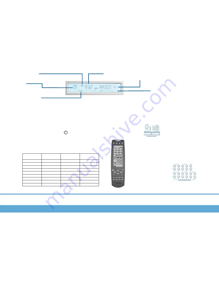
FM Stereo
Digital tuner
wave band
display
Current Source
Display
Signal Level
Note: Full 10 bars are required for optimal quality
reception
Stereo
Sound
AV1
Switch setting
Displayed
Name
AV2
Switch setting
Displayed
Name
ABC
000
001
010
011
100
101
110
111
000
001
010
100
101
111
AV1
DVD2
CD2
H-DISK
TUNER2
TV
MP3
WEB
AV2
SAT2
CD2
H-DISK
H-DISC2
TUNER2
CABLE
VCR
ABC
AV1 and AV2 naming
On the rear of the MCU small DIP
switches (shown left) allow you to
choose the name that appears when
AV1 and AV2 sources are selected.
Use the table on this page to set up
your custom names.
Note: To re-name these sources the DIP switches must be
changed with the MCU turned off.
1= On
0= Off
000= Default
Adding additional source equipment
Connect new source equip-
ment to the source inputs on
the rear of the MCU500 using
good quality phono/RCA inter-
connect cables.
Installing IR codes for your new source
First teach the LRC500 learning
remote control the IR commands for
your new source. See the LRC500
manual for further details
.
Next use the cloning operation to down-
load the new codes to the MCU500. To
perform this connect the LRC500 to
the MCU via the mini-jack to mini-DIN
cloning cable. The IR indicator on the
MCU will illuminate showing cloning is
active.
Press the TRANSMIT button on the
LRC500 for three seconds. You will
hear a beep and the transmit mode
screen will appear.
Press each flashing number in order
until they have disappeared. The device
screen displays the ‘Tx’ icon.
Press the LRC500’s
button to start the
transmitting operation.
The LRC500 ‘Tx’ icon and the MCU’s IR
indicator will flash.
When the data is transfered the ‘Tx’
icon will stop flashing.
Exit the transmit mode by pressing the
LEARN button. Three beeps will be
heard.
110
LRC500/AV1/AV2 Naming/Adding additional source equipment
Содержание LRC500
Страница 11: ...11 Notes...


