background image


OP-10STX | Manuel d’installation et d’utilisation | Installation and user manual |                                   

21 


3. Installation 
 
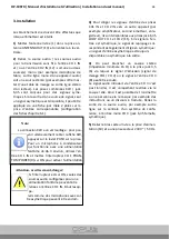
Always switch off the transmitter before making 
any connections.


1)  Insert  the  antenna  (1)  provided  into  the  an-
tenna  jack  ANTENNA  OUT  (13)  and  put  it  in  a  
vertical position.


2Connect  the  audio  source  /  sources  for  wire-
less  transmission  to  the  input  CH  1  IN  and/or 
the


input CH 2 IN (12): either one or two mono 

source  /  sources  (e.  g.  desk  microphone,  mono 
line output of an audio unit) or a stereo source 
(e.  g.  master  output  of  a  mixer  or  stereo  line 
output of a player). The combined XLR / 6.3mm 
jacks  are  designed  for  balanced  signals.  If  only 
an  unbalanced  signal  is  available  at  the  output 
of the signal source, use a 2-pole 6.3 mm plug to 
feed  it  to  the  corresponding  input  jack. 
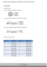
(Configuration of the plugs chapter 6.1.)


3)  To route the input signals of the jacks CH 1 IN 
and CH 2 IN to another unit (e. g. amplifier, sec-
ond transmitter, recorder), the signals are availa-
ble at the 6.3 mm jacks LOOP OUT CH 1 and


CH 2 (11). If the signal at the input is balanced, 
the corresponding feed-through signal routed


out is also balanced; an unbalanced input signal 
is always unbalanced at the output.


4)  The 3.5 mm jack (6) allows connection of ste-
reo headphones (minimum impedance 16 Ω) to 
monitor  either  the  transmission  signal  (mixed 
signal CH 1 / CH 2) or the signal at the input CH3 
(8). The audio signal fed in via the input CH 3 is 
not  transmitted  but  only  reproduced  via  the 
headphones  connected.  Thus,  you  will  be  able 
to give instructions or a speech to be translated 
to  someone  via  headphones.  Connect  the  out-
put of the audio source, e. g. line output at the 
control  panel  of  a  conference  system,  to  the 
mono input CH 3 (6.3 mm jack, unbal.).


5)  Connect  the  power  supply  unit  provided  to 
the power supply jack (10), then connect it to a 
mains socket (230 V~ / 50 Hz). 


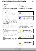
Attention, warning, danger: 


When the switch is set to ON, only con-
nect audio sources designed for a 
phantom power to the input CH 1 IN. 
Other units, e. g. microphones with un-
balanced output, may be damaged.


Note: 


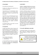
The  XLR  connection  has  a  latching  mecha-

nism.  To  remove  the  XLR  plug  later, 
press the PUSH lever at the jack. For a 
condenser  microphone  operating  at  a 
phantom  power  of  approx.  46  V  ,  use 
the  input  CH  1  IN  and  set  the  switch 

CH  1  PHANTOM  POWER  (9)  to  ON  to  activate  the 
phantom power for the input.


Содержание OP-10STX

Страница 1: ...EN FR Manuel d installation et d utilisation OP 10STX Installation and user manual OP 10STX Système de transmission UHF Wireless UHF system Emetteur fixe Stationary transmitter ...

Страница 2: ...OP 10STX Manuel d installation et d utilisation Installation and user manual 2 ...

Страница 3: ...4 2 3 Conseil d utilisation et sécurité 4 2 4 Commandes connecteurs et indicateurs 5 3 Installation 7 4 Connexions 8 5 Fonctionnement 9 6 Spécifications 11 Manual EN 15 1 Introduction 16 1 1 Purpose 16 1 2 Targeted audience 16 1 3 Alert 16 1 4 Icons 16 1 4 1 Icons et notes 16 1 4 2 Attention warning and danger incons 16 1 5 Conversion tables 17 2 Description 18 2 1 The range 18 2 2 OP 10TSX 18 2 3...

Страница 4: ...OP 10STX Manuel d installation et d utilisation Installation and user manual 4 ...

Страница 5: ...FR Manuel d installation et d utilisation OP 10STX Système de transmission UHF Emetteur fixe Français ...

Страница 6: ... rel Attention La non observance d une alerte de type atten tion peut entraîner des dommages matériels Avertissement La non observance d une alerte de type avertissement peut entraîner des dommages matériels et corporels graves Danger La non observance d une alerte du type danger peut entraîner la mort 1 4 Icônes 1 4 1 Icônes et notes Les icônes utilisées avec les notes fournissent un complément d...

Страница 7: ...t pensés pour se complé ter entre eux grâce à des caractéristiques acoustiques technologiques ou mécaniques as surant leur comptabilité 2 2 OP 10STX L émetteur rackable OP 10STX permet de trans mettre une modulation audio d une sonorisa tion ou d un micro vers un ou plusieurs récep teurs de type OP 10R ou OP 10SRX L émetteur OP 10STX constitue avec le récep teur de poche portable OP 10R un système...

Страница 8: ...aucun cas de produits chimiques ou d eau Nous déclinons toute responsabilité en cas de dommages matériels ou corporels consécutifs si les appareils sont utilisés dans un but autre que celui pour lequel ils ont été conçus s ils ne sont pas correctement branchés ou utili sés ou sʼils ne sont pas réparés par une per sonne habilitée de même la garantie devien drait caduque 2 4 Commandes connecteurs et...

Страница 9: ...ono au canal d en trée CH 3 par exemple branchement a la sortie ligne d une centrale de système de conférence le signal de cette entrée n est pas transmis il est uniquement restitue via la sortie casque 6 9 Interrupteur pour activer une alimentation fantôme 46 V environ pour l entrée CH 1 IN 12 conseil attention chapitre 4 10 Prise d alimentation pour brancher le bloc secteur livre 11 Sorties pour...

Страница 10: ... est également dirigé en symétrique un signal dʼentrée asymétrique est toujours disponible en asymétrique à la sortie 4 On peut brancher un casque stéréo impédance minimale 16 Ω à la prise jack 3 5 6 via lequel le signal d émission signal de mixage CH1 CH 2 ou le signal à l entrée CH 3 8 peut être écouté Le signal audio introduit via lʼentrée CH 3 nʼest pas transmis il est uniquement restitué via ...

Страница 11: ...hes XLR et jack Fréquences de transmission Canal Fréquence Canal Fréquence 0 863 125 MHz 8 864 125 MHz 1 863 250 MHz 9 864 250 MHZ 2 863 375 MHz A 864 375 MHZ 3 863 500 MHz B 864 500 MHz 4 863 625 MHZ C 864 625 MHz 5 863 750 MHz D 864 750 MHz 6 863 875 MHz E 864 875 MHz 7 864 000 MHz F 865 000 MHz ...

Страница 12: ...le En cas de surcharge la LED rouge brille en continu Tournez alors le réglage en conséquence dans l autre sens 3 Sur chaque récepteur TG 10R 1 on peut ré gler individuellement le volume de restitution via un réglage 4 Apres le fonctionnement pour éteindre l émetteur maintenez la touche POWER 2 briè vement enfoncée jusqu à ce que les affichages s éteignent N oubliez pas déteindre également chaque ...

Страница 13: ...tionné la LED CH 3 brille 2 Pour régler le volume du casque tour nez le bouton en conséquence Attention avertissement danger Ne réglez jamais le volume trop fort Un volume trop élevé peut à long terme générer des troubles de l audi tion L oreille s habitue à des volumes élevés et ne les perçoit plus comme tels au bout d un certain temps Nous vous conseil lons donc de régler le volume et de ne plus...

Страница 14: ...veau d entrée nominal Niveau d entrée max Branchement 20 kΩ 100 mV 1 V Prise XLR jack 6 35 femelles sy métriques Entrée CH 3 Impédance Niveau d entrée Branchement 47kΩ 250 mV Prise jack 6 35 femelle asymé trique Alimentation fantôme CH 1 46V env commutable Sortie casques Branchement Impédance casque Prise jack stéréo 3 5 femelle 16Ω Température fonc 0 40 C Alimentation Par bloc secteur livré relié...

Страница 15: ...EN Installation and user manual OP 10STX UHF transmission system Stationary transmitter English ...

Страница 16: ... type alert does not result in any material or bodily injury Attention Failure to observe a caution alert may result in property damage Warning Non compliance with a type alert Warning may result in serious personal injury and property damage Danger Failure to observe a danger alert may result in death 1 3 Icons 1 4 1 Icons and notes Icons used with notes provide additional infor mation about it S...

Страница 17: ... non metric units using the following information Table 1 lenght units conversion Table 2 Mass units conversion Table 3 Pressure units conversion Table 4 temperature units conversion 25 40 mm 25 4 mm 1 mm 1 00000 25 40 mm 2 54 cm 1 cm 0 3937 po 30 48 cm 0 3048 m 1 m 3 281 pd 1 ml 1 609 km 1 km 0 622 ml 1 lb 0 4536 kg 1 kg 2 2046 lb 1 psi 68 95 hPa 1 hPa 0 0145 psi Note 1 hPa 1 mbar F 9 5 C 32 C 5 ...

Страница 18: ...ements are thought to comple ment each other thanks to acoustic technologi cal or mechanical characteristics ensuring their accounting 2 2 OP 10STX The OP 10STX rackmount transmitter is used to transmit audio modulation from a sound system or microphone to one or more receivers of type OP 10R or OP 10SRX With the OP 10R hand held receiver the OP 10STX transmitter is a wireless mono audio transmiss...

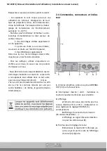
Страница 19: ...ee claims for the units and no lia bility for any resulting personal damage or ma terial damage will be accepted if the units are used for other purposes than originally intend ed if they are not correctly connected or oper ated or if they are not repaired in an expert way 2 4 Controls connectors and indicators 1 Transmitting antenna connected to the jack ANTENNA OUT 13 on the rear panel 2 On off ...

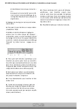
Страница 20: ...ect a mono audio source to the input channel CH 3 e g connection to the line output of the control panel of a conference system the signal of this input will not be transmitted but only repro duced via the headphone output 6 9 Switch to activate a phantom power approx 46V for the input CH 1 IN 12 caution note in chapter 4 10 Power supply jack to connect the power supply unit provided 11 Feed throu...

Страница 21: ...eed through signal routed out is also balanced an unbalanced input signal is always unbalanced at the output 4 The 3 5 mm jack 6 allows connection of ste reo headphones minimum impedance 16 Ω to monitor either the transmission signal mixed signal CH 1 CH 2 or the signal at the input CH3 8 The audio signal fed in via the input CH 3 is not transmitted but only reproduced via the headphones connected...

Страница 22: ...s and 6 3 mm plug Transmission frequencies Channel Frequency Channel Frequency 0 863 125 MHz 8 864 125 MHz 1 863 250 MHz 9 864 250 MHZ 2 863 375 MHz A 864 375 MHZ 3 863 500 MHz B 864 500 MHz 4 863 625 MHZ C 864 625 MHz 5 863 750 MHz D 864 750 MHz 6 863 875 MHz E 864 875 MHz 7 864 000 MHz F 865 000 MHz ...

Страница 23: ...ed until the display light goes off Remember to switch off each receiver OP 10R to save the battery If the transmitter is not in use for a longer peri od of time disconnect the power supply unit of the transmitter from the mains socket Even when the transmitter is switched off the power supply unit has a low power consumption 5 1 Setting the transmission channel For wireless transmission 16 channe...

Страница 24: ...edance Rated input level Input level max Connection 20 kΩ 100 mV 1 V XLR 6 3 mm jacks balanced Input CH 3 Impedance Input level Connection 47kΩ 250 mV 6 3 mm jack unbalanced Phantom power CH 1 approx 46V env to be actived Headphone output Connection Headphone impe dance Pr3 5 mm stereo jack 16Ω Ambient temperature 0 40 C Power supply Via power supply unit provided and connected to 230V 50 Hz Dimen...

Страница 25: ...OP 10STX Manuel d installation et d utilisation Installation and user manual 25 ...

Страница 26: ..._________________________________________ ___________________________________________________________________ ___________________________________________________________________ ___________________________________________________________________ ___________________________________________________________________ ___________________________________________________________________ __________________...

Страница 27: ..._________________________________________ ___________________________________________________________________ ___________________________________________________________________ ___________________________________________________________________ ___________________________________________________________________ ___________________________________________________________________ __________________...

Страница 28: ...te 2017 11 manuel d installation et d utilisation installation and user manual OP 10STX Pour toutes questions complémentaires contacter nous For any questions contact us OPUS TECHNOLOGIES ZI LAGRANGE II 9 Chemin de la Vieille Ferme 33650 MARTILLAC Tel 09 81 24 00 06 Fax 09 82 63 22 56 contact opus technologies fr ...

Отзывы: