background image

Top Panel

3

ANTENNA INPUT:

50 Ohm BNC input.  

CI-5 INPUT:

This port is used for Reaction Tune.   See Reaction Tune on pages 
9&10 for more information regarding this feature and a list of receivers 
that are compatible with the Spectrum Scout. 

9-12VDC:

Power input. AC90 9-12VDC wall adapter.  

RS232

This port is used for direct connection to a PC for uploading frequencies 
to a database, memory download and datalogging.  This port is also used 
when interfacing to the ICOM PCR100/1000 for the purpose of 
Reaction Tuning. 

CALIBRATION:

The calibration adjustment hole is located to the left of the 
Optoelectronics logo on the front panel.  The calibration is set at the fac-
tory and should not be altered.  Altering the adjustment can result in 
inaccurate frequency measurements.    

Содержание Spectrum Scout

Страница 1: ...160 West Camino Real 233 Boca Raton FL 33432 Telephone 954 642 8997 Fax 954636 3533 sales optoelectronics com www optoelectronics com Copyright 2008 OPTOELECTRONICS ...

Страница 2: ...Spectrum Scout USER MANUAL ...

Страница 3: ...tarted 4 Function Button 5 8 Reaction Tune 9 10 Memory Download and Datalogging 11 Upload a Database 12 Specifications 13 What to Expect 14 Antennas and Accessory Recommendations 15 Factory Service Warranty 16 Optoelectronics ICOM AOR Microsoft are registered trademarks ...

Страница 4: ...ry or inter nal batteries from the application of excessive voltage or show other evidence of misuse or abuse Optoelectronics reserves sole right to make this determination NON WARRANTY Products not under warranty must be returned transportation prepaid to Optoelectronics service center Factory service will be performed on a time and materials basis at the service rate in effect at the time of rep...

Страница 5: ... 165MHz RD440 440 480MHz RD800 500MHz 1GHz RD2400 2400MHz 2500MHz TA100S 100MHz 600MHz CELL LOCK 800MHz 2GHz FILTERS The N100 FM broadcast notch filter will remove the influence of local FM stations 88 108MHz pro viding up to 30dB of attenuation SERIAL DATA INTERFACE The Spectrum Scout incorporates an RS232 interface for the purpose of interfacing to a PC The fre quencies saved to memory may be do...

Страница 6: ...t and will not be covered under warranty Units returned for warranty service that have damage resulting from excessive supply voltages will incur service charges WARNING Maximum antenna input signal is 15dBm 50mW Under no circumstances should the Spectrum Scout be directly connected to an RF transmitter or be used in close proxim ity to a radio transmitter of more than 5 watts Damage to the input ...

Страница 7: ...and 50KHz steps You may also move in steps of 1 5 and 10MHz This allows for easy lookup of the FCC bandplan information A great feature of the Spectrum Scout is its ability to allow the user to upload their own frequencies for their specific location Using simple text files and and an upload program that is supplied by Optoelectronics you can easily load your own information for specific frequenci...

Страница 8: ...r less in a high RF environment High power transmitters such as FM stations TV stations Paging towers etc have an adverse influ ence on the way a frequency counter works Even if the Spectrum Scout does not lock onto and display the frequency of your local radio station that does not mean that it is not influenced by the RF Because the RF is still present the Optoelectronics N100 FM notch filter sh...

Страница 9: ...olution 1kHz 250 000 or 100Hz 250 0000 Display 2x16 alphanumeric LCD with EL Backlight Timebase 10MHz Size 3 5 H x 3 W x 1 5 D Weight 12 oz Battery Internal 5 cell AA NiCads Charging Time 8 10 hours Operating Time 4 5 Hours Power AC90 adapter supplied Power Connector 2 1 mm coax center positive Specifications ...

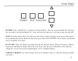
Страница 10: ...ress and hold the button and at the same time press either the UP DOWN arrow button to manually store a frequency to memory FUNCTION Press the button to navigate through the different modes When in frequency display mode press and hold the button down and at the same time press the UP DOWN arrow button to change the screen from signal strength display to FCC bandplan display UP DOWN ARROW Use thes...

Страница 11: ...er RS232 This port is used for direct connection to a PC for uploading frequencies to a database memory download and datalogging This port is also used when interfacing to the ICOM PCR100 1000 for the purpose of Reaction Tuning CALIBRATION The calibration adjustment hole is located to the left of the Optoelectronics logo on the front panel The calibration is set at the fac tory and should not be a...

Страница 12: ...pecific channel in a channelized radio service An example is Marine VHF Channel 16 In a CHANNEL database record the START FREQUENCY and the END FREQUEN CY are the same It is OK to have more than one database record for the same frequency or band of frequencies and frequency bands and channels may overlap The Spectrum Scout will display up to eight database matches for a given frequency Each USER d...

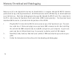
Страница 13: ... software is included with the purchase of the CBDS 1 Plug the RS232 cable into the RS232 jack located on top of the Spectrum Scout The inter face cable has a 3 5mm stereo plug on one end and a DB9 connector on the other end Plug the end with the DB9 connector into an available com port on your computer If your com puter only has a USB port then it may be necessary to obtain a serial to USB adapte...

Страница 14: ...d the POWER button for 2 seconds until the backlight turns on If the backlight is on press and hold the POWER button for 2 seconds to turn it off Display Options When powered on the Spectrum Scout defaults to signal strength mode The unit can display either signal strength or FCC bandplan data Press and hold the FUNCTION button and then press either the UP DOWN arrow buttons to switch between the ...

Страница 15: ... multiple records for a particular frequency in memory the display will change every two sec onds to display the different records Clear Memory To clear all frequencies saved to memory press and hold the FUNCTION button and then press the the UP arrow button twice in succession Auto Store The Spectrum Scout can be set to automatically store frequencies and other data to memory Press either the UP ...

Страница 16: ...n the back of the receiver Since the PCR1000 has no hardware volume or squelch controls the Spectrum Scout is capable of controlling these functions as well See page 7 for details Cables Required For Reaction Tune ICOM OptoScan and Optoelectronics Optocom CBCI5 Optoelectronics R11 CBRT AOR AR8000 RT8000 AOR AR8200 RT8200 ICOM PCR1000 CBPCR IMPORTANT The Spectrum Scout must send an initialization c...

Страница 17: ...yed It must display Reaction Tune 3 Press the FUNCTION button until Receiver Type is displayed There are three options A CI5 Following are the current CI 5 compatible receivers that the Spectrum Scout is capable of Reaction Tuning ICOM R10 R20 R7000 R7100 R8500 and R9000 Radio Shack PRO 2005 2006 with OS456 Lite installed Radio Shack PRO 2035 2042 with OS535 installed Optoelectronics R11 and Optoc...

Страница 18: ...ettings for FINE tune 1 5 6 25 10 12 5 25 30 and 50kHz Press either the UP DOWN arrow button to switch between the different options Once a step size is chosen this is the step size in which the unit will move when scrolling through the database in the previous step Resolution There are two possible resolution measurements 1kHz 250 000 fast and 100Hz 250 0000 slow Press the UP DOWN arrow button to...

Страница 19: ...r Type CI5 for ICOM and Optoelectronics receivers AR8000 for AOR receivers and PCR1000 PCR1000 Volume When interfaced to an ICOM PCR1000 in Reaction Tune mode you may control the volume of the receiver by pressing the UP DOWN arrow buttons PCR1000 Squelch When interfaced to an ICOM PCR1000 in Reaction Tune mode you may control the squelch level of the receiver by pressing the UP DOWN arrow buttons...

Страница 20: ...abase and the other two available databases have no data or are not enabled if they do have data then the Spectrum Scout will not display any FCC bandplan data when the unit locks on a signal User 1 DB To upload data to the USER DB 1 location please see page 12 and our web site for more informa tion You may choose to ENABLE all three databases If so then the DEFAULT DB will display first the USER ...

Отзывы: