Optilia Flexia BGA Скачать руководство пользователя страница 8


6. How to inspect BGA solders  
 

Turn on Flexia. Put the PCB on the stand base. Adjust height of the Rack 
& Pinion roughly. Use the Rack & Pinion unit to slide down Flexia to a few 
millimeters above the BGA package. “Fine adjust” position of BGA 
package against optical head of Flexia BGA and move down Flexia BGA 
slightly and carefully to contact with the PCB surface. Do not press BGA 
lens to the PCB.  


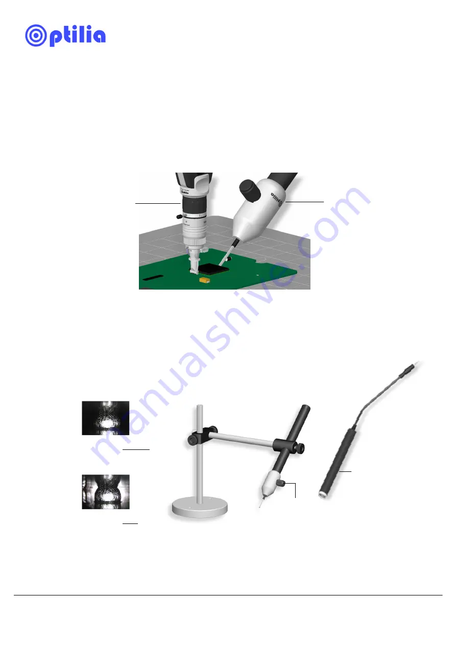
Tilt the Brush-Light approximately 45º and position tip of the optical fibers 
to edge of the BGA component by adjusting the Brush Light Stand. Turn 
on the Brush Light to insert background illumination underneath BGA 
component. Adjust intensity of the background Illumination by turning the 
Brush-Light knob.  


Note:

 Brush-Light is powered by battery or by Flexia. Switch battery tube with 

DC-adapter (optional) and connect it to AUX output of Flexia cable to power the 
illumination via Flexia Cable. Power supply must be connected to Flexia Cable!     

1.

 Move down 

Flexia BGA gently 
to get in touch with 
the PCB surface 
next to the BGA 
package.  

2.

 Tilt the Brush 

Light appr. 45 deg. 
and position tip of 
the optical fibers to 
edge of the BGA 
component.   

4.

  Turn on the light and 

adjust illumination intensity.  

3.

  Loosen locking screws and move the 

brush light toward the BGA package.   


Solder ball without 
background light   

Solder ball with 
background light   

DC-adapter  
  

Содержание Flexia BGA

Страница 1: ...1 Instructions Manual Flexia BGA Inspection Systems This manual describes how to use Flexia BGA Inspection System Optilia Instruments AB ...

Страница 2: ... About Flexia BGA 4 3 Mounting Flexia BGA 5 4 How to attach Background Illumination 6 5 How to calibrate magnifications of BGA lens in OptiPix 7 6 How to Inspect BGA solders 8 7 Zoom Focus and Image tilt adjustments 9 8 Changing Optical Head 9 9 Notes 10 ...

Страница 3: ...alcohol for cleaning optical surfaces of the device Never use Acetone or other similar solvents for cleaning Never knock or drop the video microscope Keep video microscope away from direct sun light heat and extreme humidity Store the equipment inside case when not used Protect the BGA lens Objective lens and Zoom lens by the supplied protection Rubber Caps or store them inside their boxes when th...

Страница 4: ...or TV Flexia BGA digital is plugged to PC or laptop via USB2 0 In addition Flexia analogue can also be connected to a Laptop or PC via Optilia s High speed USB2 0 or FireWire Frame Grabbers For installation of Flexia digital or Frame Grabber drivers to your computer please refer to instructions manual of the specific devise PC Lap top direct USB2 0 port TV External Display PAL NTSC PC Lap top via ...

Страница 5: ...nnect the dissipative mat to GND for ESD protection Connect Flexia to Power and monitor if analogue sensor or to USB2 0 port of your PC if digital sensor Install Flexia Digital drivers first before connecting the device to PC 2 Gently push the BGA lens inwards to click Snap position 1 Remove the protecting caps from Flexia and BGA lens first 3 Connect to Earth for secure ESD protection 2 Lock Brus...

Страница 6: ... of the BGA lens and fix it by tightening the screw Plug the DC connector into AUX output of Flexia Cable for power Loosen the illumination position screw to move illuminator forward backward Pull down optical head gently until contact with the PCB surface Light intensity is controlled by dimmer knob Insert BGA lens into the ring Position set screw Loosen screw to move illuminator forward Dimmer k...

Страница 7: ... of the die Fix position of the Zoom ring to the first magnification and move the calibration scale forward backward and or sideways until you achieve a sharp picture of the printed scales on the glass substrate If available use of XY table is preferred c Calibrate this magnification and do same procedure for other magnifications Note Accuracy of the calibration and dimensional measurements is hig...

Страница 8: ...rt background illumination underneath BGA component Adjust intensity of the background Illumination by turning the Brush Light knob Note Brush Light is powered by battery or by Flexia Switch battery tube with DC adapter optional and connect it to AUX output of Flexia cable to power the illumination via Flexia Cable Power supply must be connected to Flexia Cable 1 Move down Flexia BGA gently to get...

Страница 9: ...derneath the BGA component 8 Changing Optical Head of the BGA lens Optical Head of BGA lens can be replaced in case of damage or aging Note Micro prisms on the tip of the Optical head are protected by mechanical housing These can still be damaged if pressed against hard edges 1 Move down Flexia to contact with PCB surface BGA lens must be at 90o to the PCB 2 Rotate Zoom Ring to alter object distan...

Страница 10: ...10 9 Notes ...

Страница 11: ...11 ...

Страница 12: ... to strictly comply with Optilia Instruments AB s operating and maintenance instructions Optilia Instruments AB shall not be liable for any damages or problems arising from the use of any options or any consumable products other than those designated as original Optilia products or Optilia approved products by Optilia Instruments AB Optilia Instruments AB shall not be held liable for any damages r...

Отзывы: