3
D113727#2
+
-
20
+
-
20
+
-
20
+
-
20
+
-
20
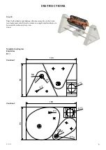
Ø 15
Ø 3
20
32
20
3
12
10
40
50
3
12
20
62
Ø 3,3
Ø 3
M4
Ø 15
Ø 3
20
32
20
3
12
10
40 50
3
12
20
62
Ø 3,3
Ø 3
M4
INSTRUCTIONS
Step 6:
Screw both screws into the two feet a
+ b. Countersink the screw head into
the pre-drilled blind hole.
.
Step 7:
Glue the two spool carriers (2) to a
solar cell (1) as shown. Let the glue
dry well!
Step 8:
Sharpen the tip of both nails (6)
cleanly with a workshop file. Shorten
both nails(6) with side cutters to 20
mm as shown. De-burr the cut-off
ends thorougly.
Step 9:
Shorten the brass tube (4) with a
fretsaw or hacksaw to 80mm. De-burr
the ends of the tube thoroughly. De-
burr the tube openings from both si-
des with the countersink. Insert both
nail tips (see Step 8) as shown into the
brass tube, so that they stick out on
both sides by approx. 5mm.
Step 10:
Clamp the nail to the end of the brass
tube by pressing down hard with the
pliers. Repeat at the other end.
Step 11:
Stick the metal motor axle from one
side through the central drill hole in
the spool carrier as shown. Stick the
tow distancer disks (5) on to the mo-
tor axle as shown and feed the other
end of the axle through the middle
drill hole in the second spool carrier
(2). Centre the axle and fix the two
distancer disks (5) by pressing them
to the spool carrier.
Step 12:
Glue the second solar cell (1) with
glue to the spool carriers (2) as
shown. Let the glue dry thoroughly!
Step 13:
Cut off four lengths of approx. 40mm
wire (11), strip both ends and tin. Sol-
der one cable each to the connectors
of the solar cells.


