background image

3–8 • Configuration

CES-8940 User Manual (Iss. 02)
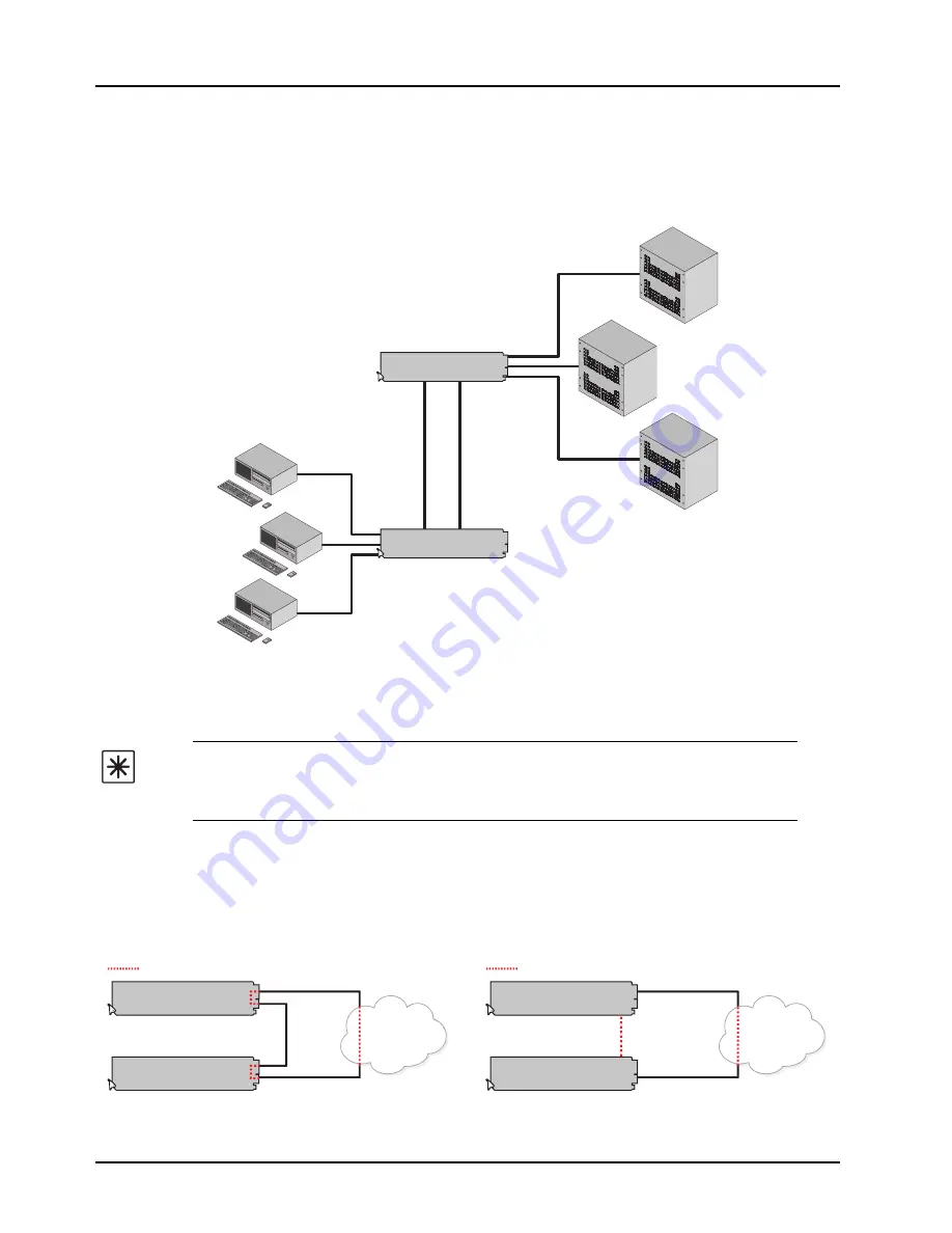
Enabling Trunking

Trunking, also known as link aggregation, is the use of two or more links between nodes 
(switches and/or servers) in parallel to increase the bandwidth. A side benefit is that a failure of a 
link will cause the traffic to be redistributed among the remaining links, though at reduced overall 
capacity.

Figure 3.7  

Multiple Cards set to Trunk for Increased Bandwidth Between End Points

A Word About Loops

If you have two or more CES-8940 cards (

Figure 3.8

) or an MFC-8322-N with one or more 

CES-8940 cards (

Figure 3.9

), there is potential to create multiple paths between devices, causing 

loops that can bring down a network. If one or more CES-8940 cards are going to connect to the 
same network, ensure that the internal GigE ports to those cards are turned off by the Network 
Controller Card. This Internal Loop issue cannot occur with an MFC-8322-S or DFR-8321 series 
frames.

Important

 — Each CES-8940 defaults as a basic switch where all ports are 

enabled and assigned to VLAN 1. If the card is wired for VLAN and/or trunking, but is 
not configured as such, you may create a possible network loop which will impact 
your network.

Figure 3.8  

Example of a Trunking Group with a Loop

Figure 3.9  

Example of a Trunking Group with a Loop

CES-8940

SER

VER

3

SER

VER

1

SER

VER

2

CES-8940

USER

GR

OUP 1

USER

GR

OUP 2

USER

GR

OUP 3

Trunk

Corporate

Network

CES-8940

CES-8940

Loop present

Corporate

Network

MFC-8322-N

CES-8940

Internal Link

Loop present

Содержание CES-8940

Страница 1: ...CES 8940 Five Port Ethernet Switch User Manual...

Страница 2: ...eople that make things happen At Ross our employees are a special group Our employees truly care about doing a great job and delivering a high quality customer experience every day This code of ethics...

Страница 3: ...itted in any form or by any means mechanical photocopying recording or otherwise without the prior written permission of Ross Video While every precaution has been taken in the preparation of this doc...

Страница 4: ...t avoided may result in major or minor equipment damage or a situation which could place the equipment in a non compliant operating state ESD Susceptibility This symbol is used to alert the user that...

Страница 5: ...has been tested to CISPR 22 1997 along with amendments A1 2000 and A2 2002 and found to comply with the limits for a Class A Digital device Maintenance User Serviceable Parts Routine maintenance to t...

Страница 6: ...ral resources Ross Video encourages you to use the appropriate take back systems These systems will reuse or recycle most of the materials from your end of life equipment in an environmentally friendl...

Страница 7: ...1K0 Ogdensburg New York Canada USA 13669 0880 General Business Office 1 613 652 4886 Fax 1 613 652 4425 Technical Support 1 613 652 4886 After Hours Emergency 1 613 349 0006 E mail Technical Support t...

Страница 8: ......

Страница 9: ...Module 2 3 Cabling for the CES 8940 2 5 Cabling Overview 2 5 Ethernet Communications Overview 2 6 Ethernet Cabling Overview 2 6 Internal GigE Link 2 6 Software Upgrades 2 7 Configuration 3 Card Overv...

Страница 10: ...CES 8940 User Manual Iss 02 Setup Tab 4 5 Alarm Enable Tab 4 6 Specifications 5 Technical Specifications 5 2 Service Information 6 Troubleshooting Checklist 6 2 Bootload Button 6 2 Warranty and Repair...

Страница 11: ...amily of products backed by Ross Video s experience in engineering and design expertise since 1974 You will be pleased at how easily your new CES 8940 fits into your overall working environment Equall...

Страница 12: ...any need for users to access the back of the openGear frame Features The following features are standard for the CES 8940 Compliant with IEEE 802 3 10 100 1000BASE T Supports 10 100 10001 Base T Ether...

Страница 13: ...orkflow of the CES 8940 Figure 1 1 CES 8940 Simplified Block Diagram CARD CONTROL AND MONITORING 10 100 1000 ETHERNET SWITCH ETHERNET PORT 4 ETHERNET PORT 3 ETHERNET PORT 2 ETHERNET PORT 1 Internal Li...

Страница 14: ...The front edge of the CES 8940 includes an LED indicator for power status LEDs on the rear module indicates communication and traffic activity For More Information on the card edge LEDs refer to the...

Страница 15: ...2 N unless otherwise noted OG3 FR series refers to all versions of the OG3 FR frames and any available options unless otherwise noted openGear frame refers to the DFR 8321 series and the OG3 FR series...

Страница 16: ...1 6 Introduction CES 8940 User Manual Iss 02...

Страница 17: ...s instructions for installing the Rear Module s for the CES 8940 installing the card into the frame cabling details and updating the software The following topics are discussed Before You Begin Instal...

Страница 18: ...tems are included If any items are missing or damaged contact your sales representative or Ross Video directly Important Contact your IT Department before connecting to your facility network to ensure...

Страница 19: ...ule Label is self adhesive by checking the back of the label for a thin wax sheet You will need to remove this wax sheet before applying the label in order that the label can be affixed to the rear mo...

Страница 20: ...lots covered with Rear Modules or Blank Plates To install the card in an openGear frame 1 Locate the Rear Module you installed in the procedure Installing a Rear Module 2 Ensure that the Rear Module i...

Страница 21: ...cables according to the following sections Cabling Overview In the openGear frames the CES 8940 is used with the 8320AR 056 Full Rear Module Each rear module occupies two slots and accommodates one c...

Страница 22: ...ure 2 3 There is no need for a crossover cable as the rear modules include an Auto MDIX ethernet PHY that will switch from straight to crossover automatically as needed Ross Video does not supply thes...

Страница 23: ...s a list of the compatible cards based on the card selected in step 2 Specify the card s to upload the file to by selecting the check box es for the cards you wish to upload the file to Verify the car...

Страница 24: ...2 8 Installation CES 8940 User Manual Iss 02...

Страница 25: ...This Chapter This chapter provides a general overview of the user controls and configuration options available for your CES 8940 The following topics are discussed Card Overview Control and Monitoring...

Страница 26: ...nformation on the LEDs available on the card edge refer to the section Control and Monitoring Features on page 3 3 Figure 3 1 CES 8940 Components 1 Bootload Button SW3 SW3 is used for factory service...

Страница 27: ...card edge report on a specific RJ45 port for your card Table 3 1 outlines the mapping of the LEDs Table 3 1 Port LED Mapping LED Reports Status of PORT 7 Internal Link PORT 6 Not implemented PORT 5 No...

Страница 28: ...When unlit this LED indicates a lack of power to the card SFP These LEDs are not implemented PORT SPEEDa a Note that Ports 5 and 6 are not implemented Green When lit green this LED indicates the port...

Страница 29: ...reen this LED indicates communication activity is occurring on the specified RJ45 port Off When unlit this LED indicates an invalid link is detected on the specified RJ45 port Verify the cable connect...

Страница 30: ...3 5 shows a simple connection where each VLAN terminates in a single device or isolated subnet Unlike Figure 3 4 there is no requirement for additional setup of the Corporate Network as the 5 Port Et...

Страница 31: ...al ports on your card 3 To assign ports on the card to a VLAN Locate the VLAN area of the Setup tab Select the applicable VLAN check box for each port you wish to include 4 For each VLAN you wish to a...

Страница 32: ...t can bring down a network If one or more CES 8940 cards are going to connect to the same network ensure that the internal GigE ports to those cards are turned off by the Network Controller Card This...

Страница 33: ...dundancy or for high bandwidth traffic You can have two or more ports acting as a trunk group to increase the bandwidth between two points The trunk appears as one port in the generic switch mode of o...

Страница 34: ...le Trunking check box 3 In the Port Enables area select the required check boxes to activate the specified RJ45 ports on your card 4 To configure a Trunk Group Locate the Trunking area of the Setup ta...

Страница 35: ...failures Once an alarm is enabled the applicable Link Status fields in the Signal tab will report when the card detects an invalid or absent connection for that link To verify which connection to tro...

Страница 36: ...3 12 Configuration CES 8940 User Manual Iss 02...

Страница 37: ...apter briefly summarizes the menus items and parameters available from DashBoard for the CES 8940 Note that default values are indicated with an asterisk The following topics are discussed Status Tabs...

Страница 38: ...but the corresponding alarm is disabled in the Alarm Enable tab Link Failure Red The link for the specified port is invalid fails and the corresponding alarm is enabled in the Alarm Enable tab Interna...

Страница 39: ...headroom Processing power available RAM available On board processing memory available Uptime h Displays the number of hours since the last reboot of the card Configuration Bank Storage count Table 4...

Страница 40: ...lignment errors RX Errors Reports the number of packets received by the specified port that have either an FCS error or an alignment error RX Dropped Reports the number of good packets received by the...

Страница 41: ...ecified ports into Trunk Group 2 Cleared Excludes the port from Trunk Group 2 VLAN RJ45 Internala a Note that a minimum of two ports must be assigned to a VLAN in order to establish communications VLA...

Страница 42: ...report when the specified ethernet port on the rear module loses network connection Cleared Disables this alarm for the specified port Internal Link Fails Selected Enables the Internal Link Status fi...

Страница 43: ...ications 5 1 Specifications In This Chapter This chapter includes the technical specifications for the CES 8940 Note that specifications are subject to change without notice The following topics are d...

Страница 44: ...the technical specifications for the CES 8940 Table 5 1 CES 8940 Technical Specifications Category Parameter Specification Ethernet 10 100 1000 Number of Ports 4 Cable Type Standard straight through...

Страница 45: ...CES 8940 User Manual Iss 02 Service Information 6 1 Service Information In This Chapter This chapter contains the following sections Troubleshooting Checklist Warranty and Repair Policy...

Страница 46: ...er supplies are fully seated in their slots If the power LED is still not illuminated replace the power supply with one that is verified to work 3 Input Signal Status Verify that source equipment is o...

Страница 47: ...ES 8940 User Manual provides all pertinent information for the safe installation and operation of your openGear Product Ross Video policy dictates that all repairs to the CES 8940 are to be conducted...

Страница 48: ...trade show information Visit Us Visit our website for Company information and news Related products and full product lines Online catalog Testimonials Technical Support Telephone 1 613 652 4886 After...

Отзывы: