


ONLINE ELECTRONICS LTD
ID5000A_5001_A03
Page 11 of 21
3.4.
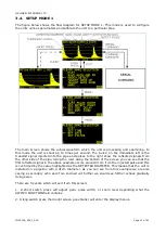
SETUP MODE 1
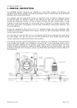
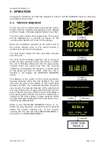
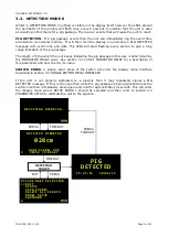
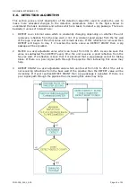
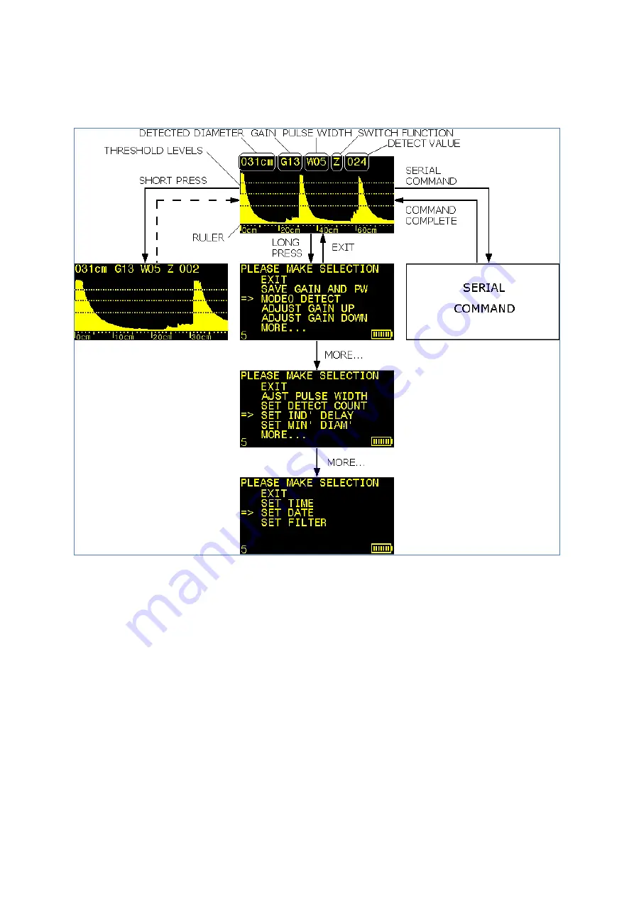
The figure below shows the flow diagram for SETUP MODE 1. This mode is used to configure
the units various parameters and calibrate the unit to a particular pipe.
The main screen shows the actual waveform which the unit is processing and examining. In
this mode th
e unit is shooting 10 times per second. The ‘pulse’ on the immediate left is t
he
transmit signal injected into the pipe and pulses to the right show the reflected signals from
the other side of the pipe. Using the ruler along the bottom of the screen you can see that the
first reflected signal in the above example occurs around 31cm from the injected pulse and this
is confirmed by the value highlighted as the DETECTED DIAMETER. This means that the unit is
installed on a pipeline with a 31cm diameter. As you can see from this example we are also
seeing a secondary echo and if we zoomed out further we would see further echoes gradually
dying away.
There are 3 events which will exit from this screen:
1. A short switch press will adjust gain, pulse width, or zoom level depending what the
SWITCH FUNCTION field contains.
2. A long switch press (held until screen goes blank) will enter the display menus.


