High
Technology
Medical
Devices
6
|
Sreznevského
17,
831
03
Bratislava,
Slovakia
Tel:
+421
2
446
409
77
;
Mobile:
+421
948
610
228,
+421
903
114
944
;
Mail:
Web:
www.onkocet.eu
Functional
scheme
of
SVIT
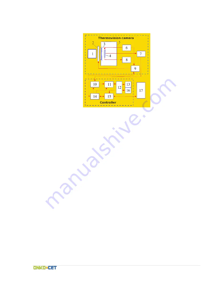
Fig.
2.
The
simplified
scheme
of
the
complete
device
set
1
‐
lens,
2
‐
the
calibration
device,
3
‐
cold
diaphragm,
4
‐
matrix
[FPU],
5
‐
vacuum
cryostat
with
the
clear
window,
6
‐
generator
of
the
managers
of
pulse
and
constant
stresses,
7
‐
amplifier
with
the
differential
output,
8
‐
temperature
gauge
[FPU]
‐
the
automatic
weapon
of
the
switching
on
of
the
bias
voltage
of
the
InAs
base
layer,
9,14
‐
units
for
control
and
synchronization,
10
‐
ACP,
11
‐
adder,
12
‐
dispatcher
of
memory,
13,16
‐
memory
banks,
15
‐
unit
of
connection
to
the
computer,
17
‐
the
computer
The
thermal
radiation
of
the
observed
scene
is
focused
by
lens
(1)
to
the
matrix
of
hybrid
microcircuit
(4),
established
in
the
vacuum
cryostat
(5).
The
level
of
background
gating
is
limited
by
cold
diaphragm
(3).
All
constant
and
surge
voltages
necessary
for
the
work
of
photoreceiver
device
are
assigned
by
generator
(6).
The
device
of
calibration
consists
of
two
mobile
shutters
(specular
and
black),
controlled
by
electromagnets.
Electromagnets
are
governed
by
the
block
(9),
which
also
transfers
into
the
block
(14)
the
pulses,
which
synchronize
the
work
of
ATsP
(10),
adder
(11),
USB
connection
unit
via
USB
port
(15)
and
block
of
the
transmission
of
information
about
the
state
of
automate
(8).
Signal
from
the
matrix
photoreceiver
device
will
be
given
to
the
entrance
of
amplifier
(7).
The
amplified
useful
signal
is
transferred
to
the
personal
computer
after
processing
in
the
controller
(10
16).
On
the
housing
of
infrared
camera
there
are:
the
ring
of
image
focusing,
USB
2.0
port
for
the
connection
to
the
computer,
connector
for
synchronization
(7
‐
pin
connector)
and
fastening
for
the
installation
of
camera
to
the
stand.
The
indicator
of
the
readiness
of
instrument
for
the
work
is
installed
near
the
neck
of
cryostat.
Содержание SVIT
Страница 1: ......


