background image

Setting the Output Conditions

312

ZW User's Manual

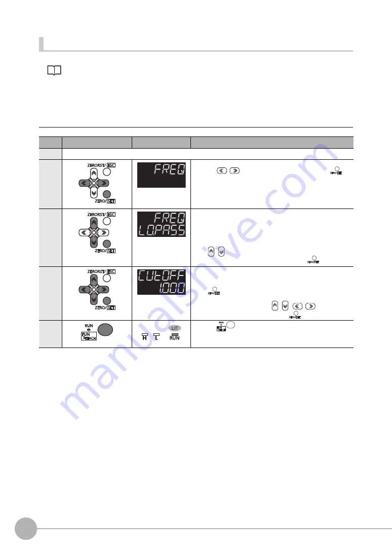
Setting the Frequency Filter

Setting the Frequency Filter p.96

As an example, here is an explanation of the procedure for selecting the "LOPASS" setting for the frequency 

filter type, and the "1Hz" cut-off frequency filter setting. 

Operating procedure

Steps

Key operation

Display

Description

1 to 4

For moving to "FILTER", see steps 1 to 4 in p.310

5

Select "FRQNCY" as the filter type.
Press the 

/

 keys to select "FREQ" and press the 


key. 

6

Select the frequency filter type.

LO.PASS: LOWPASS FILTER
HIPASS: HIGHPASS FILTER
BD.PASS: BANDPASS FILTER

Select "LOPASS" as the frequency filter type.
The current setting value is displayed on the sub-display.

Press 

/

 key to enter editing mode and the sub-display blinks.

In this example, select "LO.PASS" and press the 

 key. 

7

Set the cut-off frequency. 
"CUTOFF" is displayed on the main display and the current setting 
value is displayed on the sub-display. 

Press 

 key to enter the editing mode, and the sub-display 

blinks.

To edit numerical values, use the 

/

/

/

 keys.

In this example, input "1", then press the 

 key. 

8

Press the 

 key for two seconds to enter the RUN mode. 

Содержание ZW-C1*AT

Страница 1: ...Displacement Sensor ZW series Confocal Fiber Type Displacement Sensor User s Manual Z332 E1 07 ZW CE1 T ...

Страница 2: ...required for using the ZW When using the ZW be sure to observe the following The ZW must be operated by personnel knowledgeable in electrical engineering To ensure correct use please read this manual thoroughly to deepen your understanding of the product Please keep this manual in a safe place so that it can be referred to whenever necessary ...

Страница 3: ...ease Read Basic configuration Installation and Connections Basic Operation Settings for Function Convenient Functions Communications with External Devices Offline Settings Confocal Fiber Type Displacement Sensor ZW Troubleshooting Sensor controller operations APPENDICES ...

Страница 4: ...ying Product or iii repay or credit Buyer an amount equal to the purchase price of the non complying Product provided that in no event shall Omron be responsible for warranty repair indemnity or any other claims or expenses regarding the Products unless Omron s analysis confirms that the Products were properly handled stored installed and maintained and not subject to contamination abuse misuse or...

Страница 5: ...ucts Omron Companies shall not be responsible for the user s programming of a programmable Product or any consequence thereof Disclaimers Performance Data Data presented in Omron Company websites catalogs and other materials is provided as a guide for the user in determining suitability and does not constitute a warranty It may represent the result of Omron s test conditions and the user must corr...

Страница 6: ...example safety ultralow voltage circuit to prevent a high voltage from being generated Route so that power supply wires are as short as possible Use a power supply dedicated for this product without sharing it with other products Tighten fixing screws securely at a torque specified in this manual Before performing any of the following activities be sure to turn off the product or breakdown may res...

Страница 7: ...ety circuits involving human lives Do not attempt to disassemble repair modify apply pressure to deform or burn up the body Dispose of this product as industrial waste Use exclusive devices including a sensor head Calibration ROM fiber cable or RS 232C cable to connect or ignition burst false operation or breakdown may be caused Do not cut fiber cable Glass at the cut section may cause injury Also...

Страница 8: ...s applied circuit parts may be burnt or rupture Use the Extension Fiber Cable ZW XF R for extending the fiber cable between the Sensor extension fiber cable five total lengths 2 5 10 20 or 30 m are available Handling fiber cables Use them in compliance with the following This may result in damage to the fiber cable Fiber cable bend radiuses must be at least 20 mm Do not let bending cause stress at...

Страница 9: ...t install the Sensor Head in a place where strong light hits the laser emitter receiver section of the Sensor Head Also if an object has a shiny surface the light from the lighting will be reflected and a malfunction may occur In such a case prevent reflection by for example covering the light to stop reflection Basic precautions for installation p 30 7 Influence by Air Turbulences Slow air turbul...

Страница 10: ...ions and other contents of this manual are subject to change for improvement without notice Every effort has been made to ensure the accuracy of the contents of this manual but if you should notice any mistake questionable section or the like in this manual please contact an OMRON branch or sales office If you do so please also tell us the manual number which is found at the end of the manual Rela...

Страница 11: ...on 22 Connection Compatibility 23 2 2 Part Names and Functions 25 Sensor Head 25 Calibration ROM 25 Sensor Controller 26 2 3 Installation 30 Installation of Sensor Head 30 Installation of Sensor Controller 35 Connecting Calibration ROM 37 Connecting Fiber Cable 38 Calibrating Sensor Head 42 2 4 Wiring 44 32 pole extension connector 44 Analog output terminal block 46 24 V input terminal block 47 El...

Страница 12: ... the Area Mode 74 Setting the Material of the Target to Measure 75 Setting the Noise Cut Level 76 Setting Smoothing Size 77 Setting Start Direction of Count Measurement Surfaces 78 Setting Exposure Time Control Mode 79 Setting the Measurement Area 80 4 2 Setting Measurement Items 83 What is a Measurement Item 83 Measuring the Height 83 Measuring the Thickness 85 Performing Calculations 86 4 3 Sett...

Страница 13: ...ommunications with External Devices 6 1 Parallel I O connection 138 I O Signal Functions 138 Settings for Analog Output 140 Settings for Judgment Output 145 Settings for Processing When Measurement Is Not Possible 148 Settings for Bank Control 150 Settings for Internal Logging 151 Timing Chart 152 6 2 EtherCAT Connection 159 Overview of EtherCAT Networks 159 ZW Communications Methods in an EtherCA...

Страница 14: ...ror Messages 270 Errors for EtherCAT Connection Sysmac Error Status 270 Errors for EtherCAT Connection SDO 281 Errors for Ethernet or EtherNet IP Connection 282 Errors Common to All Communication States 283 8 2 Troubleshooting 284 9 Sensor controller operations 9 1 Search from Menu Tree 288 FUN Mode Menu 288 RUN run Mode Menu 293 9 2 Functions of Operating Keys 294 9 3 Digital Displays 295 9 4 Swi...

Страница 15: ...allel I O 338 Settings for Analog Output 338 Settings for Judgment Output 342 Settings for Processing When Measurement Is Not Possible 344 Setting for Internal Logging 346 9 13 Connecting with EtherCAT 348 Setting Fieldbus 348 Setting GATE Signal ON Time 349 9 14 Connecting with EtherNet IP 350 Network Settings of the Sensor 350 Setting Fieldbus 351 9 15 Connecting by No protocol Communications 35...

Страница 16: ...ne ZW 381 10 3 Processing Item Data List 384 10 4 System data list 388 10 5 Object Dictionary 390 Object Dictionary Area 390 Data type 390 Description Format of Objects 391 Communication Object 392 PDO Mapping Object 395 Sync Manager Communication Object 399 Manufacturer Unique Objects 402 Index 443 Revision History 446 ...

Страница 17: ...ZW User s Manual 1 15 ...

Страница 18: ...uring the Thickness p 85 p 306 Calculating p 86 p 307 Setting the Filter p 93 p 310 Setting the Scaling p 87 p 314 Setting the Hold p 98 p 318 Setting the Zero Reset p 105 p 322 Changing the Bank Mode p 110 p 327 Copying the Bank System Settings p 111 p 328 Bank Settings only Saving the Bank System Settings p 112 p 329 Clearing the Bank Settings p 113 p 330 Checking Information p 114 p 334 Setting...

Страница 19: ...1 Basic configuration Basic configuration 1 1 ZW series Displacement Sensors 18 1 2 Basic Operation Flow 19 ...

Страница 20: ... C1 AT ZW CE1 T I O Specifications EtherCAT and EtherNet IP not mounted Binary output device mounted EtherCAT and EtherNet IP mounted Binary output device not mounted PC tool Sysmac Studio Measurement Sensor Edition Smart MonitorZW version 1 10 or later Sysmac Studio Standard Edition Sysmac Studio Measurement Sensor Edition Smart MonitorZW version 1 10 or later Sensor head Sensor Controller PC too...

Страница 21: ...set Set the Zero Reset Saving the setting data 1 Save the set data Setting measurement items Select task s from TASK1 to TASK4 and set measurement items including height thickness and calculation Setting Measurement Items Setting the Output Conditions Installation and Connections Section 2 Installation and Connections Section 4 Settings for Functions Section 4 Settings for Functions 4 3 Setting th...

Страница 22: ... Communications Using Ethernet IP Communications Using Ethernet RS 232C Communications Setting the Banks Setting the System Environment 3 6 Setting Threshold Value 6 1 Parallel I O connection 6 2 EtherCAT Connection 6 3 Ethernet IP Connection 6 4 No protocol Connection 3 4 Bank Switching 3 5 Perform the Zero Reset Section 3 Basic Operation Section 6 Communications with External Devices 4 4 Setting...

Страница 23: ...2 Installation and Connections Installation and Connections 2 1 System Configuration 22 2 2 Part Names and Functions 25 2 3 Installation 30 2 4 Wiring 44 2 5 Installing the Sysmac Studio 51 ...

Страница 24: ...RJ45 RJ45 Other EtherCAT slaves General purpose USB Cable General purpose Ethernet Cable Industrial EtherNet IP Ethernet Switching Hub Sysmac Studio Standard Edition 1 NJ series Machine Automation Controller NJ series Machine Automation Controller EtherCAT Master EtherCAT Master Parallel Cable Parallel Cable Parallel Cable If you use Smart Monitor ZW Connect the PC and the ZW to control 24 V power...

Страница 25: ...tions Sysmac Studio Standard Edition The Sysmac Studio provides an integrated development environment for the NJ series Controllers and other Machine Automation Controllers and EtherCAT Slaves It supports setup programming debugging operation and maintenance The Sysmac Studio Standard Edition DVD includes Support Software for EtherNet IP DeviceNet serial communications and PT screen design CX Desi...

Страница 26: ...System Configuration 24 ZW User s Manual EtherCAT Junction Slave GX JC03 3 ports type GX JC06 6 ports type Used to connect multiple sensors or PLCs using EtherCAT Product Model Application ...

Страница 27: ...the Calibration ROM is not connected an error is displayed No Names Functions 1 Projector receiver Projects and receives light 2 Serial number Serial number Only a calibration ROM with the same serial number is available 3 Fiber interface Interfaces the Sensor Head and optical fiber unremovable 4 Fiber Cable Sends or receives light signals to from the Sensor Controller 5 Fiber Connector Couples th...

Страница 28: ...nd Functions 26 ZW User s Manual Sensor Controller 1 2 3 4 5 6 27 25 9 10 11 17 12 15 22 26 23 24 21 20 19 16 18 30 29 28 13 14 31 8 7 Front view Display Rear view Bottom view 32 Control Panel Connectors terminals ...

Страница 29: ... shows measured values and or function names 8 Sub display green The sub display shows additional information for measured values or setting values for functions 9 RUN indicator green The RUN indicator is lit in the RUN mode and goes out in the FUN mode 10 THRESHOLD L indicator orange The LOW threshold value indicator is lit when the Sub display indicates a LOW threshold value 11 THRESHOLD H indic...

Страница 30: ...t to EtherCAT compatible devices Use the recommended EtherCAT cable 24 EtherCAT input output connector This connector is used to connect to EtherCAT compatible devices Use the recommended EtherCAT cable 25 24 V input terminal block This connector is used to connect to Sensor Controller DC24 V power supply The length of Cables should be less than 30 m 26 32 pole extension connector This connector c...

Страница 31: ...ror or communications data error Double flash Application WDT timeout ON PDI WDT timeout L A IN indicator Green OFF Link not established in physical layer Flickering In operation after establishing link ON Link established in physical layer L A OUT indicator Green OFF Link not established in physical layer Flickering In operation after establishing link ON Link established in physical layer The ti...

Страница 32: ... Basic precautions for installation Do not install the Sensor Head in a place where strong light hits the laser emitter receiver section of the Sensor Head Also if an object has a shiny surface the light from the lighting will be reflected and a malfunction may occur In such a case prevent reflection by for example covering the light to stop reflection 1 Place the Sensor Head with an appropriate d...

Страница 33: ...nter distance 20 mm Measurement center distance 7 mm NEAR side 1 mm Measuring center 0 mm FAR side 1 mm Measuring range Measurement center distance 30 mm NEAR side 3 mm Measuring center 0 mm Measuring center 0 mm FAR side 3 mm Measuring range Measuring range ZW S20 ZW S30 ZW S40 Measurement center distance 40 mm NEAR side 6 mm Measuring center 0 mm FAR side 6 mm Measuring range NEAR side 0 3 mm FA...

Страница 34: ...ement center distance 20 mm Measuring center 0 mm Measuring center 0 mm Measuring range Measuring range Measuring range NEAR side 0 3 mm FAR side 0 3 mm ZW SR07 ZW SR20 NEAR side 1 mm FAR side 1 mm ZW SR40 Measurement center distance 40 mm NEAR side 6 mm Measuring center 0 mm FAR side 6 mm ...

Страница 35: ...ence When using two or more Sensor Heads next to each other mutual interference will not occur if other beam spots are outside the areas in the following diagrams Straight type 6 7 mm ZW S07 0 6 mm 1 6 mm 19 mm ZW S20 2 mm 3 0 mm 27 mm ZW S30 6 mm 4 8 mm ZW S40 34 mm 12 mm 6 0 mm ...

Страница 36: ...Installation 34 ZW User s Manual Right angle type ZW SR07 ZW SR20 ZW SR40 6 7 mm 0 6 mm 1 6 mm 19 mm 2 mm 3 0 mm 34 mm 12 mm 6 0 mm ...

Страница 37: ... the Sensor Controller clear by 30 mm or more on its top and by 10 mm or more from either side To secure the Sensor Head and cables connected safely keep the front of the Sensor Controller clear by 65 mm or more If more than one Sensor Controller must be placed in parallel place them 10 mm or more apart each other keep them clear by 30 mm or more on their top and 30 mm or more under them Do everyt...

Страница 38: ...ontroller make sure that it is securely fixed Removal procedure 1 Hook the upper edge of the Sensor Controller s back slot onto the upper edge of the DIN track 2 Push the Sensor Controller down onto the DIN track until the DIN track attachment hook is locked Push in until you hear a click sound 1 Pull DIN track attachment hook downwards using a slotted screwdriver or an equivalent 2 Lift up the Se...

Страница 39: ...n error is displayed Only a calibration ROM and Sensor Head with a same serial number are compatible When connecting a calibration ROM with a Sensor Head make sure that they have a same serial number or measurement cannot be performed correctly 1 Drill four installation holes on the base For the location installation holes see the external dimensions 10 1 Specifications and External Dimensions p 3...

Страница 40: ...ate the convex section on the fiber cable with the groove on the fiber connector and turn the threaded section clockwise while pushing in see figure 1 In the No good status in figure 2 and figure 3 optic signals cannot be transmitted and correct measurement is not possible Always check that the system is in the Good status Protective cap Fiber connector Protective cap Fiber cable Important Fiber c...

Страница 41: ...vailable cleaner exclusive for fiber or dry and soft cloth Do not use a cloth moistened with alcohol or the dirt may be reattached We recommend the following product as the fiber cleaner Use the optional ZW XCL when cleaning the groove of the fiber connector Fiber connector cleaner p 376 The fiber cable and fiber connectors should not be left with their protective caps removed not even for a short...

Страница 42: ...m ZW XF30R 30 m Model ZW XFC Extension fiber cable ZW XF R 2 m 5 m 10 m 20 m 30 m Connection adapter ZW XFC Mate the convex section on the fiber cable with the groove on the connection adapter and turn the threaded section clockwise while pushing in Sensor Head fiber cable In the No good status in figure below optic signals cannot be transmitted and correct measurement is not possible Always check...

Страница 43: ... touched or soiled wipe the dirt away using a commercially available cleaner exclusive for fiber or dry and soft cloth Do not use a cloth moistened with alcohol or the dirt may be reattached We recommend the following product as the fiber cleaner Use the optional ZW XCL when cleaning the groove of the fiber connector Fiber connector cleaner p 376 The fiber cable and fiber connectors should not be ...

Страница 44: ...ime The Sensor Head should be calibrated without any object within the measuring range or with the tip of the Sensor Head shielded from light with an object with diffuse reflection Correct calibration is not possible with a transparent object semi transparent object or mirror Explorer pane Device Group Sensor Name System System Data double click Edit pane Sensor Settings icon 1 Set the operation m...

Страница 45: ...If this happens chack the environment and try again If an error continues even after calibrating the Sensor Head in an appropriate environment the fiber connector on the Sensor Head or Sensor Controller may be stained Clean the fiber cable or fiber connector referring to p 39 Calibrating Sensor Head can also be set by the operating keys on the Sensor Controller Calibrating Sensor Head p 336 Import...

Страница 46: ...onnector on the Sensor Controller is viewed from front Color 1 Signal name No 2 Signal name Color 1 Blue COM_IN1 B16 A16 NC Blue Green TIMING1 B15 A15 NC Green Yellow RESET1 B14 A14 NC Yellow Orange ZERO1 B13 A13 NC Orange Red LED OFF1 B12 A12 NC Red Brown COM_OUT1 B11 A11 NC Brown Black HIGH1 B10 A10 NC Black White PASS1 B9 A9 NC White Gray LOW1 B8 A8 NC Gray Purple ALARM B7 A7 NC Purple Blue BUS...

Страница 47: ...urement setting If this RESET input switches ON while the hold function is used the state in effect before the hold function was set will be restored TIMING input This is a signal input from an external device that is used to time the hold function with the continuous measurement function enabled This is a signal input from an external device that is used to time the measurement with the trigger m...

Страница 48: ... 10 V as the voltage value When measurement not possible Approx 10 8 V default value can be selected by user Alarm Approx 10 8 V OUT1 A This outputs the measured value from 4 mA to 20 mA as the current value When measurement not possible Approx 21mA default value can be selected by user Alarm Approx 21 mA OUT1 0V 0 V for analog voltage output 1 Loosen the two fixing screws using a screwdriver to r...

Страница 49: ...ide the Sensor Controller is being accessed This may corrupt the data Securely fasten the terminal block to prevent injury when you press in the release button with a screwdriver The length of Cables should be less than 30 m 2 Push in and hold the release button next to the terminal hole using a screwdriver while pushing the wire fully into the terminal hole and remove the screwdriver After the co...

Страница 50: ...to the terminal hole using a screwdriver while pushing the wire fully into the terminal hole and remove the screwdriver After the connection has been established pull the wire gently to make sure that the connection has been made securely 3 Reinstall the 24 V input terminal block to the Sensor Controller Release button Terminal hole ...

Страница 51: ...annot be prevented Input signal changes of less than 100 s are ignored The input signal is applied when the same level is maintained for 100 s or longer Always use non contact relays SSR PLC transistor output for input signals If contact relays are used contact bounding may turn ON a TIMING input again during measuring Item Specifications Model ZW CE10T ZW CE15T Input type NPN PNP Input voltage DC...

Страница 52: ... value could cause damage to the output circuit Item Specifications Model ZW CE10T ZW CE15T Output type NPN PNP Output voltage DC21 6 to 30 V DC21 6 to 30 V Load current 50 mA max 50 mA max ON residual voltage 1 2 V max 1 2 V max ON leakage current 0 1 mA max 0 1 mA max Internal circuit diagram 1 Terminal name COM_OUT1 COM_OUT2 Outputterminal name HIGH1 BANK_OUT1 PASS1 BANK_OUT2 LOW1 BANK_OUT3 ALA...

Страница 53: ...s Manual 51 2 5 Installing the Sysmac Studio The PC Tool used to set up ZW series Displacement Sensors is installed from the Sysmac Studio Installer Refer to the Sysmac Studio Version 1 Operation Manual Cat No W504 for the system requirements and installation procedure ...

Страница 54: ...Installing the Sysmac Studio 52 ZW User s Manual MEMO ...

Страница 55: ...Launching a project 54 3 2 Explanation of Screen Sections 56 3 3 Switching operation modes 61 3 4 Bank switching 62 3 5 Perform the Zero Reset 65 3 6 Setting Threshold Value 68 3 7 Saving a project 70 3 8 Operating with Sensor Controller 71 ...

Страница 56: ...ectly specify the IP address of the sensor to connect Check the Specify a sensor box Then directly enter the IP address and click OK For the default value of the IP address refer to p 203 When not connected with the sensor offline When setting a project offline without connecting to the actual sensor check Enter the type to select Then select the sensor model and software version to use and click ...

Страница 57: ...ane Device Group right click Add Entering project information Comments about the project can be entered Explorer pane Device Group Sensor Name double click Edit pane General Settings icon 1 Enter comments for the project in the Comment field 4 After the sensor is connected the following window appears The Main pane appears on the Edit pane The sensor starts up in RUN mode ...

Страница 58: ...isplayed 2 Toolbar Tool functions that can be used with this tool is displayed with icons 3 Explorer pane Displays the data hierarchy of the sensor with a hierarchy tree Double clicking each data displays Main pane Bank data edit pane and System data edit pane on the Edit pane 4 Edit pane Edits and displays data selected in the Explorer pane It mainly consists of Menu icon Line bright monitor sett...

Страница 59: ...roject Rename Changes the device group name Sensor model Edit Displays the main pane as the Edit pane Delete Deletes a sensor from the project Copy Copies a sensor Online Switches the connection status with the sensor to online Offline Switches the connection status with the sensor to offline RUN Switches the sensor to RUN mode Setup Switches the sensor to Setup mode Save settings Save the sensor ...

Страница 60: ...selected with menu icons a pop up window is called out 3 Guidance The description of the focused setting item is displayed 4 Measurement value monitor The selected measurement results or output values are displayed 5 LED light The status of each LED light is displayed when online 6 I O input The status of I O signals can be switched when online 7 Line bright monitor The line bright is displayed 1 ...

Страница 61: ...ata edit pane Sensing Switching the operation mode 1 area 2 area and setting exposure time and measurement areas can be performed Task 1 Allows you to perform setting to calculate the feature amounts of height thickness and calculation using scaling filter and hold processes Settings can be made individually for the task 1 to 4 I O Allow you to make settings for judgment output and analog output S...

Страница 62: ...tart sampling Starts the sampling Stop sampling Stops the sampling Show grid Displays gridlines Show configuration Displays the logging condition setting window Show data table Displays the data window to be logged Show Analog Chart Displays the analog chart window Show Digital Chart Displays the digital chart window Import Imports the exported measurement results and display them on each chart Ex...

Страница 63: ... RUN mode when the power is turned on Explorer pane Device Group Sensor Name double click Edit pane Online icon Item Setting item Mode Description Online Operation mode RUN Switches to RUN operation mode Normal operation mode Setup Switches to Setup mode Mode for setting the measurement conditions 1 Select the operation mode with Operation mode Switching operation modes can also be set by the oper...

Страница 64: ... desired measurement items such as peak bottom and average for each task Height TASK1 Surface fluctuation TASK2 Measurement processing flow in TASK1 For the output the following four types are supported Analog output Select one TASK that you want to output Judgment output Select one TASK that you want to output Serial output Ethernet RS 232C Can output data from four tasks at a time Fieldbus outpu...

Страница 65: ...dividual banks Setting the analog output destination p 140 Sensing Filter Threshold value BANK The sensing settings for measurement are held as one bank Output I O Sensing Filter Threshold value Output I O BANK8 BANK3 BANK2 BANK1 BANK8 BANK3 BANK1 BANK2 BANK1 TASK1 TASK4 Sensing Filter Threshold value Output I O I O Sensing Filter Threshold value Output Sensing Filter Threshold value Output I O Me...

Страница 66: ...ommand p 242 SmartMonitor ZW Operation Manual 1 Click the bank group on the Explorer pane to open 2 Select the bank data to switch and double click or right click it to select the Edit menu The bank in the Bank data edit pane that is active on the Edit pane becomes the current bank Switching Banks can also be set by the operating keys on the Sensor Controller Switching Banks p 326 Important Note ...

Страница 67: ... output as a positive or negative deviation tolerance from the set reference value 0 Example 1 Use the height of the sensing object as a reference value and the deviation is the measured value Example 2 Use the measured value according to the height of the sensing object set 10 as an offset value 2 HIGH threshold value 2 LOW threshold value Sensor head 0 reference value Sensing object 10 12 HIGH t...

Страница 68: ...ence value to the hold value for a hold measurement or any value other than zero Setting the Zero Reset p 105 p 322 Executing Zero Reset 1 Place the reference sensing object in position 2 Press the key The ZERO indicator illuminates and the current measured value is registered as 0 Sensor head Zero reset executed Zero reset executed Zero reset executed Direction of movement This step is measured ...

Страница 69: ...e 32 pole extension connector 32 pole extension connector p 44 The Zero Reset function can also be executed by turning ON the EtherCAT ZERO input signal Zero reset execution p 166 p 173 Canceling Zero Reset The Zero Reset function can also be executed by supplying a ZERO signal to the 32 pole extension connector 32 pole extension connector p 44 ZERO input p 139 The canceling Zero Reset function ca...

Страница 70: ...utput A judgment result appears on the Sensor Controller as follows When the judgment result is HIGH HIGH indicator lights up When the judgment result is PASS PASS indicator lights up When the judgment result is LOW LOW indicator lights up HIGH ON OFF ON OFF ON OFF LOW PASS Measured value LOW threshold value HIGH threshold value Output ON when Measurement result HIGH threshold value ON when LOW th...

Страница 71: ...ues can also be adjusted by directly entering values in the RUN mode This helps you to make fine adjustments without shutting down the system Changing Threshold Values p 301 Item Setting item Setting value Description Judgment LOW threshold 999 999999 to 0 default value to 999 999999 mm Set the lower limit LOW threshold value HIGH threshold 999 999999 to 0 default value to 999 999999 mm Set the up...

Страница 72: ...le Save to select Exporting a project A project data smc can be exported The exported data can be used by importing with the other personal computer s PC tool Importing a project The exported data from other personal computers can be imported as project data Configuration data Description Project information Information on the sensor registered in this project Entire sensor information Entire sens...

Страница 73: ... 71 3 Basic Operation 3 8 Operating with Sensor Controller Other than using PC tools ZW Series can also be operated using the operation keys on the Sensor Controller For details on how to operate with operation keys see 9 Sensor controller operations ...

Страница 74: ...Operating with Sensor Controller 72 ZW User s Manual MEMO ...

Страница 75: ...4 Settings for Function Settings for Function 4 1 Setting Sensing 74 4 2 Setting Measurement Items 83 4 3 Setting the Output Conditions 87 4 4 Setting the Banks 110 4 5 Setting the System 114 ...

Страница 76: ...and the reflection characteristics of the target to measure are different The sensing setting suitable for each the measurement surface can be used 1 Select the area mode at Operating mode Area mode When the 2 area mode is selected Measurement area 2 is added to the setting items for sensing setting In the 2 area mode the exposure time control mode and measurement area must each be set for Measure...

Страница 77: ...escription Operation mode Material Normal default value A measurement can be performed at specific linearity regardless of the type of target to measure Usually select this setting Mirror Select this mode when specular reflection regular reflection occurs on the surface Glass wafer lustrous metal etc Rough Select this mode when diffuse reflection occurs on the surface 1 Select the material of the ...

Страница 78: ...orer pane Bank Bank Data Name double click Edit pane Sensing setting icon Sensing settings window Operating mode Item Setting item Setting value Description Operation mode Noise cut level 0 to 4 095 Gradation Default value 100 Set the number of gradations when noise is cut from the line bright 1 Set Noise cut level Noise Noise can be cut ...

Страница 79: ...e Bank Bank Data Name double click Edit pane Sensing setting icon Sensing settings window Operating mode Usually use the initial value because the resolution may worsen when the setting a small value Item Setting item Setting value Description Operation mode Smoothing size 1 3 5 7 9 pixels Default value 5 Set the pixel size to be used as the unit when smoothing the line bright 1 Set Smoothing size...

Страница 80: ...n Operation mode Start direction of count measurement surfaces NEAR default value Measurement surfaces are counted from NEAR side FAR Measurement surfaces are counted from FAR side The setting of start direction of count measurement surfaces can also be set by the operating keys on the Sensor Controller Setting Start Direction of Count Measurement Surfaces p 303 Example NEAR 1 surface 2 surface 3 ...

Страница 81: ...efault value Automatically sets the exposure time within the range that does not exceed the specified upper limit Usually select this setting Manual Select this mode when you want to specify the exposure time and set the exposure time fixed value Exposure time maximum 1 to 1 000 default value to 5 000 s Set the upper limit value of the exposure time when Automatic has been selected for the control...

Страница 82: ...e setting values for the measurement area satisfy the following relationship Start End To set the measurement area using any value by the above method at Measurement area 2 set Area follow at Area follow settings to OFF Item Setting item Setting value Description Measurement area Upper line Measuring range of Sensor Head mm Set the measurement start position for the selected measurement area When ...

Страница 83: ...ack the Start setting value for measurement area 1 Lower line Adjust the measurement area of measurement area 2 to track the End setting value of measurement area 1 Upper line and lower line Adjust the measurement area of measurement area 2 to track the Start and End setting value of measurement area 1 Base Edge1 Edge2 Edge3 Edge4 peak default value Edge1 Select the measurement surface of measurem...

Страница 84: ...ing 82 ZW User s Manual 1 Set Area follow 2 Set Reference surface and Following surface 3 Click Area Teach The range applied to measure the measurement surface Follow is automatically set as the measurement area 2 ...

Страница 85: ...ut result of each task Count the measurement surface closest to the Sensor Head first Measuring the Height Sensor head Edge 1st Edge 2nd Edge 3rd Edge 4th The setting for common height measurements as shown in the following diagram is registered for TASK1 in advance In such a case this setting is not required Set this item when measuring the height of an object below a transparent object as shown ...

Страница 86: ...ent area Area 1 default value Area 2 The area targeted for measurement can be switched Measurement surface Edge1 Edge2 Edge3 Edge4 peak default value The measurement surface targeted for measurement can be switched The peak is the surface of all measurement surfaces having the highest received light amount 1 Select the measurement area targeted for measurement from Measurement area 2 Select the me...

Страница 87: ... be switched The peak is the surface of all measurement surfaces having the highest received light amount Measurement surface 2 Edge1 Edge2 Edge3 Edge4 peak default value The measurement surface rear surface targeted for measurement can be switched The peak is the surface of all measurement surfaces having the highest received light amount 1 Select the measurement area targeted for measurement fro...

Страница 88: ... to be calculated can be switched Parameter Y OFF default value TASK1 to TASK4 The task to be calculated can be switched Parameter K 999 999999 to 999 999999 default value 0 Set the offset value Parameter m 0 0 to 10 0 Default value 0 Set the coefficient value Parameter n 0 0 to 10 0 Default value 0 Set the coefficient value 1 Select the task to be calculated from Parameter X and Parameter Y 2 Sel...

Страница 89: ...scaling that automatically sets the correction value of a placed sensing object transparent object The Zero reset p 65 settings return to the default settings when scaling is set If scaling is set perform a zero reset as necessary Performing Manual Scaling Set the scaling by entering the correction value Item Setting item Setting value Description Scaling Manual scaling Scaling OFF default value O...

Страница 90: ...value to Span and Offset Fixed scaling can also be executed by the operating keys on the Sensor Controller Performing Manual Scaling p 314 Item Setting item Setting value Description Actual scaling one point Set value 999 999999 to 999 999999 mm Correct the measured value and set the value to display Scaling direction Inverse change The FAR side becomes a plus value Forward change The NEAR side be...

Страница 91: ...t value 4 Click STOP to fix the Current value set Set value and click Next The Scaling popup menu display changes to Direction settings 5 Set the change direction and click Next The Scaling popup menu display changes to Confirm the scaling parameters and the span and offset values are displayed 6 Click OK 1 point scaling can also be executed by the operating keys on the Sensor Controller Performin...

Страница 92: ... mm 0 01 0 12 mm as the measuring range is 12 mm 6 mm Explorer pane Bank Bank Data Name double click Edit pane Task Settings icon Task Settings window Scaling Item Setting item Setting value Description Actual scaling two points Set value 1st point 999 999999 to 999 999999 mm Correct the measured value of the 1st point and set the value to display Set value 2nd point 999 999999 to 999 999999 mm Co...

Страница 93: ...point The Scaling popup menu display changes to Direction settings When the change direction is set and Next is clicked the Scaling popup menu display changes to Confirm the scaling parameters and the span and offset values are displayed 6 Click OK 2 point scaling can also be executed by the operating keys on the Sensor Controller Performing 2 point Scaling p 316 The current measured value is disp...

Страница 94: ...o setting The Scaling popup menu appears 3 Select Thickness scaling and click Next The Scaling popup menu display changes to Thickness settings 4 Click STOP to fix the Current value set Set value and click Next The Scaling popup menu display changes to Confirm the scaling parameters and the span and offset values are displayed 5 Click OK Thickness scaling can also be executed by the operating keys...

Страница 95: ...lter is not set 0 Median filter MEDIAN Average filter AVE Differ filter DIFFER Frequency filter FREQ Waveform when filter is not set Lowpass filter LOPASS Highpass filter HIPASS Bandpass filter BDPASS Displacement Smooth Spike like changes are removed Displacement Changes are smoothed out Changes are extracted to eliminate displacement value Sudden changes are removed Gradual changes are removed A...

Страница 96: ...alue Description Medial filter Filter mode OFF default value Median filter is not used LOW Outputs the intermediate value of the last three measurements Middle Outputs the intermediate value of the latest nine measurements HIGH Outputs the intermediate value of the last 15 measurements 1 Select how many of the latest intermediate values to output from Medial filter Filter mode The median filter ca...

Страница 97: ...s started the measurement result is not updated and output until the measured values have been sampled for the preset average count Item Setting item Setting value Description Average number of times Average 1 2 4 8 16 32 64 128 256 default value 512 1024 2048 4096 times Switches the average count 1 Select how many times the latest measured values are to be averaged before output from Average numb...

Страница 98: ...ng value Description Frequency filter Frequency filter OFF default value Frequency filter is not used Lowpass filter Ignores frequency components larger than the specified cut off frequency Only gradual changes are captured Highpass filter Detects frequency components smaller than the specified cut off frequency Sudden changes are captured Bandpass filter Detects the frequency components between t...

Страница 99: ...con Task Settings window Filter Item Setting item Setting value Description Differentiation filter Filter mode OFF default value ON Set the differentiation filter ON OFF Differentiation cycle 1 default value to 5000 ms Set the internal time for the measurement value to be compared with the current value 1 Select differentiation filter ON OFF from Differentiation filter Filter mode 2 Set the number...

Страница 100: ...state is held until the next sampling ends Peak to Peak Holds the difference between the maximum value and the minimum value of the sampling period Mainly select this when detecting vibration for example Output changes after sampling and this state is held until the next sampling ends Auto Peak Holds the maximum value of the measurement result The output changes every time the maximum value is upd...

Страница 101: ...e measured value the moment that control enters the sampling period Output changes at the start of sampling and this state is held until the next sampling is started Through default value The hold function is not used The measured value is always output 1 Select the hold mode from Hold mode Setting items for required parameters are displayed depending on the selected hold mode Setting Triggers p 1...

Страница 102: ...if an abnormal measured value is obtained set KEEP as the non measurement setting Setting operation when measurement is not possible p 148 When the hold value is reset the clamp level is output until the next hold value is applied The mode is switched between the FUN mode and RUN mode FUN mode RUN mode Sampling Sampling Hold value Measurement value Clamp level When RESET is executed 32 pole extens...

Страница 103: ...ynchronized End timing is after the sampling period has elapsed Selfdown trigger The period in which the measured value falls below the preset self trigger level is taken to be the sampling period Hold measurement can be performed without a synchronous input When a delay time is set the timing that the measured value exceeds the self trigger level and the sampling period end are not synchronized E...

Страница 104: ...el Hysteresis is applied simultaneously with start of measurement to prevent chattering of the TIMING input 1 Set the hold mode Setting the Hold Mode p 98 2 Select the trigger method from Trigger settings Trigger method 3 Enter Trigger level and Trigger hysteresis when Selfup trigger or Selfdown trigger are selected at Trigger method The trigger can also be set by the operating keys on the Sensor ...

Страница 105: ...t pane Sensor Settings icon Item Setting item Setting value Description Sensor settings Timing Reset key input OFF default value ON Enables TIMING and RESET key inputs from the Sensor Controller 1 Set the operating mode to the FUN mode 3 3 Switching operation modes p 61 2 Select ON OFF from Key input mode Timing and Reset The timing reset key input can also be set by the operating keys on the Sens...

Страница 106: ... input ON up to start of sampling Sampling time 1 to 5 000 ms default value 100ms Set to period during which sampling is to be performed 1 Set the hold mode and trigger Setting the Hold Mode p 98 Setting Triggers p 101 2 Select ON OFF from Trigger delay Trigger delay mode 3 Enter Delay time and Sampling time Set so that the delay time sampling time is shorter than the TIMING input interval When th...

Страница 107: ...enable disable of the zero reset function The status is set for each task Explorer pane Bank Bank Data Name double click Edit pane Task Settings icon Task Settings window Zero reset 1 Select ON OFF from Status The status can also be set by the operating keys on the Sensor Controller Setting the Status p 322 Important Note ...

Страница 108: ...tings icon Task Settings window Zero reset Item Setting item Setting value Description Zero reset Offset 999 999999 to 999 999999 mm default value 0 Set the offset value 1 Set Status to ON Setting the Status p 105 Offset can be set only when Status is set to ON 2 Enter an offset value at Zero reset Offset The offset can also be set by the operating keys on the Sensor Controller Setting the Offset ...

Страница 109: ...ue Sets the measured value hold value when a zero reset is executed to zero This is enabled when hold measurement is performed 1 Set Status to ON Setting the Status p 105 The zero reset type can be set only when Status is set to ON 2 Select the zero reset type from Type The zero reset type can also be set by the operating keys on the Sensor Controller Setting the Zero Reset Mode p 324 Measurement ...

Страница 110: ...ontroller each time that a zero reset is performed The EEPROM can be written a maximum of 1 000 000 times Pay attention to the maximum number of writing allowed when this is set to ON Even if zero reset memory is disabled the zero reset level will be held also when the setting is saved In this instance the zero reset will also be continued after a restart Item Setting item Setting value Descriptio...

Страница 111: ...stem double click Edit pane Sensor Settings icon 1 Set the operating mode to the FUN mode 3 3 Switching operation modes p 61 2 Select ON OFF from Zero Reset Memory mode The zero reset mode can also be set by the operating keys on the Sensor Controller Setting the Zero Reset Memory p 325 Note ...

Страница 112: ...ue Sensing setting measurement setting and I O setting that are set in the FUN adjustment mode are regarded as bank data The number of banks is up to eight Judgement value Only the threshold value under the measurement setting is regarded as bank data The number of banks increases up to 32 1 Set the operating mode to the FUN mode 3 3 Switching operation modes p 61 2 Select the bank mode from Bank ...

Страница 113: ...operation modes p 61 2 Copy the bank data or system data Select the copy source bank data or system data from the explorer pane and select Copy from the right click menu 3 Paste the bank data or system data Select the copy destination bank data or system data from the explorer pane and select Paste from the right click menu The bank settings can also be copied by the operating keys on the Sensor C...

Страница 114: ...a 1 Set the operating mode to the FUN mode 3 3 Switching operation modes p 61 Explorer pane ZW model name double click Edit pane Online icon Online setting window Save data 2 Select Save data Sensor internal memory Bank system settings are saved to Sensor internal memory Settings can also be saved by selecting and right clicking a ZW model from the explorer pane and selecting Save settings from th...

Страница 115: ...its settings 1 Set the operating mode to the FUN mode 3 3 Switching operation modes p 61 2 Select the bank data Select the bank data from the explorer pane and select Initialize from the right click menu The bank settings can also be cleared by the operating keys on the Sensor Controller Initializing Settings p 337 Note ...

Страница 116: ...lays the model information of the Sensor Controller Software Version Displays the version information of the software of the Sensor Controller Sensor head model Displays the model information of the Sensor Head Sensor serial No Displays the serial No of the Sensor Head MAC address Displays the MAC address that is set 1 The Edit pane main pane is displayed in the Edit pane You can check the above i...

Страница 117: ...r moving between menu hierarchies are possible even when the key lock function is ON by the operating keys on the Sensor Controller Explorer pane System double click Edit pane Sensor Settings icon Item Displayed item Setting value Description Sensor settings Key lock OFF default value Cancels the key lock function ON Turns the key lock function ON 1 Set the operating mode to the FUN mode 3 3 Switc...

Страница 118: ...fault values are decided by the Sensor Head measuring range HYSTERESIS TRIGGER HYSTERESIS HIGH THRESHOLD LOW THRESHOLD are all set to the factory default value 0 Explorer pane ZW model name double click Edit pane Tool icon 1 Click Sensor setup Initialize sensor Initialization is executed Item Setting item Setting value Description Sensor settings The number of decimal places 0 to 5 Digit default v...

Страница 119: ...ngs can also be initialized by selecting and right clicking a ZW model option from the explorer pane and selecting Initialize sensor from the right click menu Settings can also be initialized by the operating keys on the Sensor Controller Initializing Settings p 337 Note ...

Страница 120: ...Setting the System 118 ZW User s Manual MEMO ...

Страница 121: ...Saving measured values in a file 125 5 3 Displaying saved measured values 128 5 4 Performing internal logging 129 5 5 Storing the light reception wave form in a file 131 5 6 Recovering calibration ROM data 133 5 7 Printing the contents of settings 134 5 8 Controll input signal with PC tool 135 ...

Страница 122: ...pane ZW model name double click Edit pane Online icon Online setting window Trend Monitor 1 Click Trend Monitor Start monitor The Trend Monitor window starts up 2 Add the data to monitor the trend for Add the data to monitor the trend for to the list Click the add target data icon Click the logging target data display icon to add to the list of data to be logged A new target data line is added To ...

Страница 123: ... the graph display stops too Item Setting item Description Target data TASK1 TASK1 measurement results TASK2 TASK2 measurement results TASK3 TASK3 measurement results TASK4 TASK4 measurement results TIMING TIMING input signal parallel I O ZERO ZERO input signal parallel I O BUSY BUSY output signal parallel I O ENABLE ENABLE output signal parallel I O HIGH HIGH output signal parallel I O PASS PASS ...

Страница 124: ...y parallel I O TIMING ZERO BUSY ENABLE HIGH PASS LOW as the trigger condition Data slope Sets the change in the measured values for TASK1 4 as the start condition Sets the trigger level When the measured value rises above this value or falls below it the end trigger is issued Data window In Sets the change in the measured values for TASK1 4 as the start condition When the measured value is in the ...

Страница 125: ... condition is considered to have been met When the measurement results are less than or equal to the judgment value the trigger condition is considered to have been met Judgment 999 999999 to 999 999999 mm This is the judgment value for the measurement results Item Setting item Range Description Trigger condition Judgment value 1 999 999999 to 999 999999 mm When the measurement results are greater...

Страница 126: ...n is met input a negative value for the delay time Sampling start position B To end sampling after the time when the trigger end condition is met input a positive value for the delay time 1 Input the delay time Item Setting item Range Description Trigger condition Delay time 999 999999 to 999 999999 ms The sampling starts or ends at the time shifted by the set time from when the trigger condition ...

Страница 127: ... End button Each time the trigger start condition is met a new file is prepared and saved Save in This is the folder to save the files in File prefix This is the prefix for the name of the file saved Samples per file 100 to 10000000 This is the number of samples saved in one file If more samples than this set number are taken a new file is prepared Max sampling time 0 0 0 to 24 59 59 This indicate...

Страница 128: ...ope DataWindowIn DataWindowOut DataSize Indicates the trigger end condition IO I O result DataSlope Data slope DataWindowIn Data window in DataWindowOut Data window out DataSize Number of data points TriggerEndObject TASK1 TASK2 TASK3 TASK4 TIMING ZERO BUSY ENABLE HIGH PASS LOW Indicates the target data for the trigger end condition TriggerEndConditions EqualTo NotEqualTo AndMore MoreThan LessThan...

Страница 129: ...nnection p 138 LoggingMode Single SamplePeriod 0 0 1 0 0 TriggerStart True TriggerStartType DataSlope TriggerStartObject TASK1 TriggerStartConditions EqualTo TriggerStartValue1 1 1 TriggerStartValue2 TriggerStartDelay 0 TriggerEnd True TriggerEndType DataWindowIn TriggerEndObject TASK2 TriggerEndConditions TriggerEndValue1 0 5 TriggerEndValue2 0 5 TriggerEndDelay 0 ExternalFileStorage FALSE MaxSam...

Страница 130: ...asured values were exported and display those sampling results as a graph Explorer pane ZW model name double click Edit pane Online icon Online setting window Trend Monitor 1 Select Trend Monitor The Trend Monitor window starts up 2 Click the import icon 3 Select the file to import The file is imported and a graph displayed ...

Страница 131: ...ion Data logging conditions Preservation intervals 1 to 99999 Set the data storage interval If 1 is set all measured data is stored and 2 is set one measurement value is stored every two measurement Logging data count 1 to 12800 Set the number of data points to store for each TASK TASK1 OFF ON Set whether to store the measurement results for TASK 1 TASK2 OFF ON Set whether to store the measurement...

Страница 132: ...ta to a file A CSV format file in the following format is output LoggingMode Internal SamplePeriod 1 Index Task1 Task2 Task3 Task4 0 1 21314 1 21314 1 21314 1 21314 1 1 22098 1 22098 1 22098 1 22098 2 0 12334 0 12334 0 12334 0 12334 3 0 1211 0 1211 0 1211 0 1211 4 1 23456 1 23456 1 23456 1 23456 5 1 22222 1 22222 1 22222 1 22222 ...

Страница 133: ... Area 1 Area2 Measurement Area 2 StartPosition 0 to 255 Indicates the start position for the measurement area EndPosition 0 to 255 Indicates the end position for the measurement area 1 Select the line bright storage icon Input the name of the file to export to A CSV format file in the following format is output RegionNo Area1 StartPosition Display area start point EndPosition Display area end poin...

Страница 134: ...d point Display area end point Position Value Value 0 Amount of light received 0 Amount of light received 0 1 Amount of light received 1 Amount of light received 1 2 Amount of light received 2 Amount of light received 2 3 Amount of light received 3 Amount of light received 3 254 Amount of light received 254 Amount of light received 254 255 Amount of light received 255 Amount of light received 255 ...

Страница 135: ... sensor Explorer pane Device Group Sensor Name double click Edit pane Tool icon The calibration ROM data is different for each sensor serial number Select the backup file that matches the sensor serial number Measurement will not be correct unless they match 1 Set the operating mode to the FUN mode 3 3 Switching operation modes p 61 2 Click the ROM recovery in Sensor setup Select the calibration R...

Страница 136: ...nformation The sensor information is printed Bank Group The bank group data Banks 1 through 8 is printed Bank The specified bank data is printed System The system data is printed Bank number 1 to 8 If bank data is selected as target data specify the bank number to print the data for 1 Select Print The Print window is displayed on the Edit pane 2 Select the data to print From Target data select the...

Страница 137: ... Edit pane I O input 1 Select ON from I O input 2 If each button is clicked the Sensor Controller is controlled as corresponding input signal is turned ON While the button is clicked corresponding input signal is status ON If the button is clicked again the input signal is turned OFF Button Effect LED OFF The measurement LED is turned OFF TIMING The TIMING input is turned ON RESET The RESET input ...

Страница 138: ...Controll input signal with PC tool 136 ZW User s Manual MEMO ...

Страница 139: ...6 Communications with External Devices Communications with External Devices 6 1 Parallel I O connection 138 6 2 EtherCAT Connection 159 6 3 EtherNet IP Connection 198 6 4 No protocol Connection 226 ...

Страница 140: ...urement not possible Approx 21 mA default value can be selected by user At alarm Approx 21 mA Name Description HIGH output Judgment result HIGH HIGH threshold value measured value is output PASS Output Judgment result PASS LOW threshold value measured value HIGH threshold value is output LOW output Judgment result LOW LOW threshold value measured value is output Name Description ALARM output This ...

Страница 141: ...t output conforms to the non measurement setting If this RESET input switches ON while the hold function is used the state in effect before the hold function was set will be restored Name Description TIMING input This timing input is for signal input from external devices Use it for hold function timing Name Description LED OFF input Turn off the measurement LED While LED OFF is being input the an...

Страница 142: ...e output destination is set for all banks The output destination cannot be set separately for individual banks Explorer pane Device Group Sensor Name System System Data double click Edit pane Sensor settings icon Item Setting item Setting value Description Sensor settings Analog output Voltage output default value Voltage output Current output Current output 1 Set the operating mode to the FUN mod...

Страница 143: ...en Analog output Item Setting item Setting value Description Analog output Output object None TASK1 TASK2 TASK3 TASK4 Select the task to output as analog 1 Set the operating mode to the FUN mode 3 3 Switching operation modes p 61 2 Select the task from Output object You can select from the above setting values None TASK1 TASK2 TASK3 TASK4 Analog output can also be assigned with key operations on t...

Страница 144: ...value Sets monitor focus ON OFF Point1 Distance value 999 999999 to 3 000000 default value to 999 999999 mm Sets the reference measured value for output Current output value 4 default value to 20 mA When the analog output destination is set to current sets the current to be output when the distance value is measured Voltage output value 10 default value to 10 V When the analog output destination i...

Страница 145: ...ter 1 Set the operating mode to the FUN mode 3 3 Switching operation modes p 61 2 Select ON OFF from Monitor Focus 3 Enter the Distance and Output value at Point1 4 Likewise enter the Distance and Output value at Point2 Item Setting item Setting value Description Analog out put adjust ment Analog output adjustment ON OFF default value Set analog output correction ON OFF Point1 Reference value curr...

Страница 146: ...Analog output adjustment 3 Click Setting The Analog Output Adjust popup menu appears 4 Enter the Distance and Output value at Point1 and click Output 5 Likewise enter the Distance and Output value at Point2 and click Output 6 Click Setting Analog output values can also be adjusted with key operations on the Sensor Controller Adjusting the analog output value p 341 Note ...

Страница 147: ...utput from the following output terminals of the 32 pole extension connector HIGH1 PASS1 LOW1 Explorer pane Bank Bank Data Name double click Edit pane I O Settings icon I O Setting Screen Judgment Item Setting item Setting value Description Judgment Output object TASK1 TASK2 TASK3 TASK4 Select the task for which to output the judgment result 1 Set the operating mode to the FUN mode 3 3 Switching o...

Страница 148: ...f Delay Delays the falling edge of the PASS output by the value set at Timer Duration after the judgment result has been applied On Delay Delays the rising edge of the PASS output by the value set at Timer Duration after the judgment result has been applied ON OFF ON OFF ON OFF HIGH threshold value Measured value LOW threshold value HIGH output PASS output LOW output Hysteresis hysteresis width Ac...

Страница 149: ...uration when the timer mode is other than OFF 1 Set the operating mode to the FUN mode 3 3 Switching operation modes p 61 2 Set Hysteresis Width 3 Select the judgment output timing to match operation of the external device from Timer settings Timer mode 4 Sets Timer time The operations for judgment output can also be set with key operations on the Sensor Controller Setting Operation at Judgment Ou...

Страница 150: ...rer pane Bank Bank Data Name double click Edit pane I O Settings icon I O Setting Screen Non Measurement Setting Item Setting item Setting value Description Non Measure ment setting Non Measurement setting Keep The measured value before the non measurement state was entered is held and output Clamp With analog output the preset clamp value abnormal value is output All judgment outputs become OFF 1...

Страница 151: ... not possible can also be set with key operations on the Sensor Controller Setting operation when measurement is not possible p 344 Item Setting item Setting value Description Analog output Clamp output When the analog output destination is set to current MIN approx 3 4mA 4 to 20mA 1mA increments MAX default value approx 21mA When the analog output destination is set to voltage MIN approx 10 8V 10...

Страница 152: ...tly selected bank number The currently selected bank number is output The output bank number depends on the combination of the bank number output signals BANK_OUT1 to 3 Clamp values can also be set with key operations on the Sensor Controller Setting the Clamp Value p 345 Bank selection input 1 BANK_SEL1 Bank selection input 2 BANK_SEL2 Bank selection input 3 BANK_SEL3 Selected bank OFF OFF OFF BA...

Страница 153: ...smac Studio Item Setting item Setting value Description Internal logging LOGGING save count 0 to 12800 default value Sets the maximum data count to be internally logged LOGGING save intervals 0 to 1 default value to 1000 Sets the intervals to be internally logged If 1 is set all measured data is stored and 2 is set one measured data is stored every two measurement If 0 is set only the applied meas...

Страница 154: ... 2 After the end of exposure measurement starts 3 After the end of measurement the judgment result is output 4 After the judgment result output the analog output is updated Item Min Max T0 Measuring cycle 0 5ms Depends on the set conditions 0 5 to 10 0 ms T1 Exposure time 1 s Max exposure time 1 to 5000 s T2 Response time of output T0x2 T0x2 T3 Response time of analog output 0 1 ms 2 3 Judgment ou...

Страница 155: ...t result reset the analog output is reset 9 The RESET input is turned OFF When the setting for non measurement is CLAMP if the sampling value is an abnormal value or an undetermined value sampling is not executed If sampling has been started it is stopped The output value is as follows Hold the clamp value To start and continue sampling even if a sampling value is an abnormal value or an undetermi...

Страница 156: ...t is CLAMP if the sampling value is an abnormal value or an undetermined value sampling is not executed If sampling has been started it is stopped The output value is as follows Hold the clamp value The BUSY signal is turned OFF To start and continue sampling even if a sampling value is an abnormal value or an undetermined value set KEEP as the non measurement setting After the start of measuremen...

Страница 157: ...reset 6 After the judgment result output the analog output is reset 7 The RESET input is turned OFF When the setting for non measurement is CLAMP if the sampling value is an abnormal value or an undetermined value sampling is not executed The output value is as follows Hold the clamp value The BUSY signal is not turned ON After the start of measurement if measurement results are not obtained the n...

Страница 158: ... LED OFF input is turned OFF 5 After the LED OFF input is turned OFF the LEDs are turned ON 6 After the LEDs are lit up measurement is restarted and the ENABLE output is turned ON Item Min Max T7 Input response time 200 ms T8 Bank switching time 100 ms T9 Measurement start response time 3 T0 Depends on the set conditions Item Min Max T9 Measurement start response time 3 T0 Depends on the set condi...

Страница 159: ...output are turned OFF The judgment outputs all go OFF 2 The response time of analog output after the BUSY output is turned ON the analog output is output clamped 3 After the mode is switched from the FUN mode to the RUN mode the BUSY output is turned OFF 4 Measurement is restarted and the ENABLE signal is turned ON then the measurement results are output Item Min Max T7 Input response time 2ms T0 ...

Страница 160: ...ned ON the internal logging is started 3 The LOGGING input is turned OFF 4 After the LOGGING input is turned OFF the internal logging is ended Item Min Max T15 LOGGING input minimum time 3ms T0 T16 Input response time 2ms T0 3ms T0 2 T16 LOGGING input Operation status T16 Logging stopped state Logging in progress Logging stopped state T15 ON OFF 1 2 3 4 ...

Страница 161: ...ime from generation of input signals to transmission of output signals By fully utilizing the optimized Ethernet frame bandwidth to transfer data using a high speed repeat method it is possible to efficiently transmit a wide variety of data Extremely High Compatibility with Ethernet EtherCAT is an open network with extremely high compatibility with conventional Ethernet systems Structure of EtherC...

Страница 162: ...th header data length including address of one or more Slave Units etc data working counter check bit When an Ethernet frame is compared to a train an EtherCAT datagram can be considered as railway car Ethernet header CRC Ethernet data Maximum 1498 bytes Data Header WKC 1 n EtherCAT datagram EtherCAT header 1st EtherCAT datagram 2nd EtherCAT datagram n th EtherCAT datagram EtherCAT frame Ethernet ...

Страница 163: ...pping logical process data space to each node by the EtherCAT Master Unit it achieves fixed cycle communications among the EtherCAT Master Unit and Slave Units Mailbox communications functions SDO communications It refers to message communications At any timing the EtherCAT Master Unit transmits commands to Slave Units and the Slave Units return responses to the EtherCAT Master Unit It performs th...

Страница 164: ... by storing control signals command from the master to the displacement sensor status signals from the displacement sensor to the master and command responses to the I O ports or I O memory 1 of the Controller 1 When connected to the NJ series I O ports are used and when connected to the CJ series I O memory is used Explanations from here on are for when the connection is to the NJ series The Cont...

Страница 165: ...atus signals 1 I O ports of instruction area I O ports to which the user writes control signals to be executed on the displacement sensor and control com mands 2 I O ports of response area I O ports to which the displacement sensor writes the control signals written to the instruction area and the result of executing control commands Data output after applica tion of measured value 3 I O ports of ...

Страница 166: ...nse Execution After applying measured value Sysmac error status Command response communi cations Data output after measure ments Error status Error status information from the Displacement Sensor is written here Output data from the Displacement Sensor is written here The execution results from the Displacement Sensor are written here The following control commands are written to the Displacement ...

Страница 167: ...Range Fieldbus Select whether to use EtherNet IP communications or EtherCAT communications OFF EtherNet IP EtherCAT GATE signal ON time Set the output time of the GATE signal for notifying the timing that the measured value was updated when hold is output 0 to 100ms 1 Set the fieldbus settings Select EtherCAT at Fieldbus 2 Set the output time of the GATE signal Set the value at GATE signal ON time...

Страница 168: ...s the error signal ERR signal OFF Sensor Head1 Control Flag Sensor head 1 control signal TIMING1 TIMING1 Timing Turns ON when the user Controller instructs start of hold sampling to the displacement sensor Turns OFF when the user Controller instructs end of hold sampling to the displacement sensor RESET1 RESET1 Reset Turns ON when the user Controller instructs judgment processing and output reset ...

Страница 169: ... control command code response code and response status are stored Automatically turns OFF if the control command execution signal EXE signal from the user Controller turns OFF SYNCFLG SYNCFLG Measurement synchronization completion Turns ON when the displacement sensor executes measurement synchronization processing and the state changes to one where normal measured values can be output Automatica...

Страница 170: ...nt result Turns ON when even one of the judgment result of the displacement sensor TASK1 to 4 is other than PASS Turns OFF when all of the judgment result of the displacement sensor TASK1 to 4 is PASS HIGH1_T1 to 4 HIGH1_T1 4 HIGH output Turns ON when the judgment result of the displacement sensor TASK1 to 4 is HIGH HIGH threshold measured value Turns OFF when the judgment result of the displaceme...

Страница 171: ...OFF BANK4 ON ON OFF OFF OFF BANK5 OFF OFF ON OFF OFF BANK6 ON OFF ON OFF OFF BANK7 OFF ON ON OFF OFF BANK8 ON ON ON OFF OFF BANK9 OFF OFF OFF ON OFF BANK10 ON OFF OFF ON OFF BANK11 OFF ON OFF ON OFF BANK12 ON ON OFF ON OFF BANK13 OFF OFF ON ON OFF BANK14 ON OFF ON ON OFF BANK15 OFF ON ON ON OFF BANK16 ON ON ON ON OFF BANK17 OFF OFF OFF OFF ON BANK18 ON OFF OFF OFF ON BANK19 OFF ON OFF OFF ON BANK2...

Страница 172: ...asurement Value of Task2 TASK2 measured value 4 bytes The measured value of TASK2 is output Measurement Value of Task3 Measurement Value of Task3 TASK3 measured value 4 bytes The measured value of TASK3 is output Measurement Value of Task4 Measurement Value of Task4 TASK4 measured value 4 bytes The measured value of TASK4 is output I O port name Signal Signal name Function Sysmac Error Status Sysm...

Страница 173: ... and monitoring Explorer pane Connected to NJ series CPU Unit Configurations and Setup I O Map Double click Right click a slave or I O port in the I O map and select Create Device Variable The device variable name is automatically created as a combination of the device name and the I O port name You can also select an I O port and enter a variable name in the Variable column You can also select a ...

Страница 174: ...ed Reserved 6 Command code Command code 32bit 7 8 Parameter 1 Parameter 1 16bit 9 Parameter 2 Parameter 2 16bit 10 Parameter 3 Parameter 3 32bit 11 Signal Signal name Function EXE Control command execution Turns ON when the user PLC instructs execution of control commands to the displacement sensor Turns ON after the control command code and parameters are set Is returned to OFF on condition input...

Страница 175: ...t status of parallel I O processing is executed of one of the statuses is ON Top channel Bit Description 15 14 13 12 11 10 9 8 7 6 5 4 3 2 1 0 0 BANK1 _E BANK1 _D BANK1 _C BANK1 _B BANK1 _A Reserved Reserved Reserved Reserved Reserved Reserved RUN Reserved READY SYNC FLG FLG Sensor head common control signal 32bit 1 Reserved Reserved Reserved Reserved Reserved Reserved Reserved Reserved Reserved R...

Страница 176: ...n execution state LIGHT1 Logical beam lighting state Turns ON when the logical beam is lit Turns OFF when the logical beam is out STABILITY1 Measurement position Turns ON when the measured value is in the measuring range Turns OFF when the measured value is outside the measuring range ENABLE1 Measurement state Turns ON when the displacement sensor is ready for measurement Turns OFF when the displa...

Страница 177: ...e zero reset execution state Turns OFF when the displacement sensor TASK1 to 4 is in the zero reset non execution state Command code Command code The executed command code is returned Response code Response code The response code of the executed command is stored Response data Response data The response data of the executed command is stored Signal Signal name Function ...

Страница 178: ... OFF OFF BANK5 OFF OFF ON OFF OFF BANK6 ON OFF ON OFF OFF BANK7 OFF ON ON OFF OFF BANK8 ON ON ON OFF OFF BANK9 OFF OFF OFF ON OFF BANK10 ON OFF OFF ON OFF BANK11 OFF ON OFF ON OFF BANK12 ON ON OFF ON OFF BANK13 OFF OFF ON ON OFF BANK14 ON OFF ON ON OFF BANK15 OFF ON ON ON OFF BANK16 ON ON ON ON OFF BANK17 OFF OFF OFF OFF ON BANK18 ON OFF OFF OFF ON BANK19 OFF ON OFF OFF ON BANK20 ON ON OFF OFF ON ...

Страница 179: ...ue of Task4 Output data 3 32bit 7 8 Reserved Output data 4 32bit 9 10 Reserved Output data 5 32bit 11 12 Reserved Output data 6 32bit 13 14 Reserved Output data 7 32bit 15 Signal Signal name Function Measurement Value of Task1 Measurement Value of Task1 The measured value of TASK1 is output Measurement Value of Task2 Measurement Value of Task2 The measured value of TASK2 is output Measurement Valu...

Страница 180: ...arameters The Support Software for Position Control Units will start Set the areas and the first words for the Remote I O Output Memory Area the Axis Status Memory Area and the Remote I O Input Memory Area 3 Checking the Remote I O Area Select Network and then click the Remote I O Assignment Tab to check the I O addresses that are set for remote I O You can manually change the input offset and out...

Страница 181: ...etwork Node addresses 17 and higher will be automatically set for the remote I O For the Position Control Unit the areas are set only for node 17 which has the first area for each of the three memory areas To access data from another node from a ladder program add the correct offset from the first word of the first area for node 17 and access the resulting address Position Control Unit to ZW CIO38...

Страница 182: ...estart Restarts the displacement sensor p 182 Command area Top channel Hex Command name Function Reference Pages 7 6 0030 8000 Current bank settings Replace the current bank number by the specified bank number p 183 Command area Top channel Hex Command name Function Reference Pages 7 6 0040 1000 Processing unit data acquisition Acquires the measurement data and setting data of the processing unit ...

Страница 183: ...code 32 bit Stores the command code targeted for a response 7 0000 0000 0001 0000 8 0000 0000 0000 0000 Response code 32 bit Command execution result OK 9 0000 0000 0000 0000 8 0000 0000 0000 0001 Response code 32 bit Command execution result NG no corresponding command 9 1111 1111 1111 1111 8 0000 0000 0000 0010 Response code 32 bit Command execution result NG wrong parameter 9 1111 1111 1111 111...

Страница 184: ...00 0000 0000 0000 Response code 32 bit Command execution result OK 9 0000 0000 0000 0000 8 0000 0000 0000 0001 Response code 32 bit Command execution result NG no corresponding command 9 1111 1111 1111 1111 8 0000 0000 0000 0010 Response code 32 bit Command execution result NG wrong parameter 9 1111 1111 1111 1111 8 0000 0000 0000 0100 Response code 32 bit Command execution result NG processing ex...

Страница 185: ...0000 0000 Command code 32 bit Stores the command code targeted for a response 7 0000 0000 0011 0000 8 0000 0000 0000 0000 Response code 32 bit Command execution result OK 9 0000 0000 0000 0000 8 0000 0000 0000 0001 Response code 32 bit Command execution result NG no corresponding command 9 1111 1111 1111 1111 8 0000 0000 0000 0010 Response code 32 bit Command execution result NG wrong parameter 9 ...

Страница 186: ...ommand execution result OK 9 0000 0000 0000 0000 8 0000 0000 0000 0001 Response code 32 bit Command execution result NG no corresponding command 9 1111 1111 1111 1111 8 0000 0000 0000 0010 Response code 32 bit Command execution result NG wrong parameter 9 1111 1111 1111 1111 8 0000 0000 0000 0100 Response code 32 bit Command execution result NG processing execution error 9 1111 1111 1111 1111 8 00...

Страница 187: ... 8 7 4 3 0 6 0001 0000 0000 0000 Command code 32 bit Stores the command code targeted for a response 7 0000 0000 0100 0000 8 0000 0000 0000 0000 Response code 32 bit Command execution result OK 9 0000 0000 0000 0000 10 0000 0000 0000 0000 Response data 32 bit Acquired data 11 0000 0000 0000 0000 8 0000 0000 0000 0001 Response code 32 bit Command execution result NG no corresponding command 9 1111 ...

Страница 188: ... Response area Top channel Bit Description 15 12 11 8 7 4 3 0 6 0001 0000 0000 0000 Command code 32 bit Stores the command code targeted for a response 7 0000 0000 0101 0000 8 0000 0000 0000 0000 Response code 32 bit Command execution result OK 9 0000 0000 0000 0000 8 0000 0000 0000 0001 Response code 32 bit Command execution result NG no corresponding command 9 1111 1111 1111 1111 8 0000 0000 000...

Страница 189: ...ode 32 bit Stores the command code targeted for a response 7 0000 0000 0100 0000 8 0000 0000 0000 0000 Response code 32 bit Command execution result OK 9 0000 0000 0000 0000 10 0000 0000 0000 0000 Response data 32 bit Acquired data 11 0000 0000 0000 0000 8 0000 0000 0000 0001 Response code 32 bit Command execution result NG no corresponding command 9 1111 1111 1111 1111 8 0000 0000 0000 0010 Respo...

Страница 190: ...Description 15 12 11 8 7 4 3 0 6 0100 0000 0000 0000 Command code 32 bit Stores the command code targeted for a response 7 0000 0000 0101 0000 8 0000 0000 0000 0000 Response code 32 bit Command execution result OK 9 0000 0000 0000 0000 8 0000 0000 0000 0001 Response code 32 bit Command execution result NG no corresponding command 9 1111 1111 1111 1111 8 0000 0000 0000 0010 Response code 32 bit Com...

Страница 191: ...executed 4 When the displacement sensor completes execution the command code response code and response data are set 5 The FLG output signal turns ON 6 The Controller makes sure that the FLG output signal has turned ON and then returns the EXE input signal to OFF 7 The displacement sensor makes sure that the EXE input signal has turned OFF and the FLG and READY output signals automatically turn OF...

Страница 192: ...me control mode is fixed Set the exposure time the same for all displacement sensors for which measurement is to be synchronized By way of reference the time from acceptance of the SYNC input up to when SYNCFLG output turns ON becomes currently set exposure time upper limit 720 s After multiple displacement sensors are synchronized they gradually go out of sync At most 1 s of difference generates ...

Страница 193: ...he state of the RESETx input signal from OFF to ON At the rising edge of the RESETx input signal the displacement sensor starts the measured value reset period 8 At the start of the measured value reset period the displacement sensor changes the state of the RESETSTATx output signal from OFF to ON 9 At completion of the measured value reset the displacement sensor changes the state of the GATEx ou...

Страница 194: ...RESETSTATx from OFF to ON 5 At completion of the measured value reset the displacement sensor changes the state of the GATEx output signal from OFF to ON 6 The displacement sensor turns OFF after the GATE signal ON duration has elapsed since the GATEx output signal turned ON 7 The Controller changes the state of the RESETx input signal from ON to OFF At the falling edge of the RESETx input signal ...

Страница 195: ...he RESETx input signal from OFF to ON At the rising edge of the RESETx input signal the displacement sensor starts the measured value reset period 8 At the start of the measured value reset period the displacement sensor changes the state of the RESETSTATx output signal from OFF to ON 9 At completion of the measured value reset the displacement sensor changes the state of the GATEx output signal f...

Страница 196: ...ZEROx_T1 to 4 input signals have turned ON and then executes the zero reset 2 At execution of zero reset the displacement sensor changes the state of the ZEROSTATx_T1 to 4 output signal from OFF to ON 3 The Controller makes sure that the ZEROSTATx_T1 to 4 output signals have turned ON and then returns the ZEROx_T1 to 4 input signals to OFF 4 The Controller changes the state of the ZEROCLRx_T1 to 4...

Страница 197: ...trol the EXE signal so that it does not turn ON while the READY signal is ON If not a EXE input error will occur and the ERR signal will turn ON First RUN Period Flag Control Command Completed E001_FLG Execution condition Control Command Completed E001_FLG Command Execution Ready E001_READY Command Execution Bit E001_EXE Turns ON Command Execution Bit Command Execution Bit E001_EXE When the contro...

Страница 198: ...itch setting is 00 Software Setup mode the node address value you set in Sysmac Studio is enabled If the node address switches are set to any other value the value that is set on the switches is used as the node address In the Software Setup mode in Sysmac Studio execute Write Slave Node Address on the EtherCAT Edit screen to save the slave node address setting in the nonvolatile memory of the ZW ...

Страница 199: ...an EtherCAT slave that stores the configuration information specific to that EtherCAT slave Sysmac Device EtherCAT slaves check the SII information from the slave side If one of these slaves finds that SII information with which it cannot operate was written it generates an SII Check Error Error No 88 3 If this error persists even after turning OFF and then ON the power again contact your OMRON sa...

Страница 200: ...f the Number of Nodes Tag data links cyclic communications operate at the cyclic period that is specified for each application regardless of the number of nodes Data is exchanged over the network at the refresh cycle that is set for each connection The communications refresh cycle will not increase even if the number of nodes is increased i e the concurrency of the connection s data is maintained ...

Страница 201: ...he connection is called the originator and the node that receives the request is called the target Data Exchange Memory Locations The memory locations that are used to exchange data across a connection are specified as tags You can specify memory addresses or variables for tags A group of tags consists of an output tag set and an input tag set Displacement Sensor Connection PLC Output tag set name...

Страница 202: ...the Displacement Sensor e g perform continuous measurements or change the scene without using special communications instructions Input Connection to Sensor PLC to Displacement Sensor The commands that are stored in the I O memory of the PLC are sent to the Displacement Sensor Output Connection to PLC Displacement Sensor to PLC Responses from the Displacement Sensor to the control commands are sto...

Страница 203: ...atically to the specified I O memory of the PLC specified to the input tag To output data specify the I O memory area or a variable output area on the PLC for storing that data in advance to the input tag PLC Displacement Sensor Output area I O memory or variables communications areas EtherNet IP built in unit EtherNet IP tag data links Automatic output of measured value data of each task Output c...

Страница 204: ...ea to which the displacement sensor writes the measured value data of each task after application of the measured value 1 Command area PLC Control inputs Command code Command parameters 2 Response area 3 Output area Control outputs Command code Response code Response data Displacement Sensor Execution After applying measured value Output Tag Set Input Tags 1 Output Tags Input Tag Set Input Tag Set...

Страница 205: ...g items can be set Series CPU Unit Interface Built in port in CPU Unit EtherNet IP Unit SYSMAC NJ NJ501 or NJ301 Compatible CJ1W EIP21 SYSMAC CJ2 CJ2H or CJ2M Compatible model with built in port only CJ1W EIP21 SYSMAC CJ1 CJ1H or CJ1G CJ1W EIP21 CJ1M CJ1W EIP21 SYSMAC CS CS1H CS1D or CS1G CS1W EIP21 Item Description Setting range IP address Set the IP address of the Displacement Sensor a b c d a 1...

Страница 206: ...on To enable the settings restart the Controller The network settings of the sensor can also be set with key operations on the Sensor Controller Network Settings of the Sensor p 350 1 Select Ethernet IP at Fieldbus The setting of default settings for EtherNet IP communications can also be set by the operating keys on the Sensor Controller Network Settings of the Sensor p 350 Note Important Note ...

Страница 207: ...gurator Download the EDS file from the OMRON website After tag data links are set the Displacement Sensor will automatically be restarted to enable the settings Tags Tag Sets and Connection Settings The communications areas in the PLC are set as tag data link connections as shown in the following table Tag and Tag Set Settings in the PLC 1 Specify the I O memory address of the first word in the re...

Страница 208: ...ng is required here 1 Right click the ZW in the network on the Network Configurator and select Parameter Edit 2 The Edit Device Parameters Dialog Box will be displayed Make the required settings Parameter name Value Setting range 001 Input Size The total size of response area and output area 56 002 Output Size The data size of command area 24 003 RPI The requested packet interval 10000 ...

Страница 209: ...ges unless addresses in the CIO Area which are maintained are specified The following assembly object is required to specify instances when the EDS file is not used Assembly Object Settings Parameter Setting Originator device PLC Input tag set PLC_tag_set_name Byte This is the total size of the response area and output area that you set Connection type Any default multi cast connection 1 Output ta...

Страница 210: ...served Reserved Reserved Extended area 32bit 5 Reserved Reserved Reserved Reserved Reserved Reserved Reserved Reserved Reserved Reserved Reserved Reserved Reserved Reserved Reserved Reserved 6 Command code Command code 32bit 7 8 Parameter 1 Parameter 1 16bit 9 Parameter 2 Parameter 2 16bit 10 Parameter 3 Parameter 3 32bit 11 Signal Signal name Function EXE Control command execution Turns ON when t...

Страница 211: ...f the input status of parallel I O processing is executed of one of the statuses is ON Top channel Bit Description 15 14 13 12 11 10 9 8 7 6 5 4 3 2 1 0 0 BANK1 _E BANK1 _D BANK1 _C BANK1 _B BANK1 _A Reserved Reserved Reserved Reserved Reserved Reserved RUN Reserved READY Reserved FLG Sensor head common control signal 32bit 1 Reserved Reserved Reserved Reserved Reserved Reserved Reserved Reserved ...

Страница 212: ...nnot measure excessive or insufficient received light outside measuring range Calibration ROM not mounted during FUN mode non measurement GATE1 Data output completed Turns ON when the displacement sensor completes control data output when hold is set The displacement sensor automatically turns OFF one Gate period after turning ON OR1 Overall judgment result Turns ON when even one of the judgment r...

Страница 213: ...F OFF BANK4 ON ON OFF OFF OFF BANK5 OFF OFF ON OFF OFF BANK6 ON OFF ON OFF OFF BANK7 OFF ON ON OFF OFF BANK8 ON ON ON OFF OFF BANK9 OFF OFF OFF ON OFF BANK10 ON OFF OFF ON OFF BANK11 OFF ON OFF ON OFF BANK12 ON ON OFF ON OFF BANK13 OFF OFF ON ON OFF BANK14 ON OFF ON ON OFF BANK15 OFF ON ON ON OFF BANK16 ON ON ON ON OFF BANK17 OFF OFF OFF OFF ON BANK18 ON OFF OFF OFF ON BANK19 OFF ON OFF OFF ON BAN...

Страница 214: ...t Value of Task4 Output data 3 32bit 7 8 Reserved Output data 4 32bit 9 10 Reserved Output data 5 32bit 11 12 Reserved Output data 6 32bit 13 14 Reserved Output data 7 32bit 15 Signal Signal name Function Measurement Value of Task1 Measurement Value of Task1 The measured value of TASK1 is output Measurement Value of Task2 Measurement Value of Task2 The measured value of TASK2 is output Measurement...

Страница 215: ...tatus signals Here a data type called U_EIPFlag is defined Name of data type U_EIPFlag Type of derivative data type Union 2 Defining Data Types for Communications Area Access Data types are defined to access the communications areas with one data type for the command area and another data type for the response and output areas Here data types called S_EIPOutput and S_EIPInput are defined Data Type...

Страница 216: ...RCLR TIMING 1 RESET 1 ZERO CLR_T4 ZERO CLR_T3 ZERO CLR_T2 ZERO CLR_T1 ZERO1 _T4 ZERO1 _T3 ZERO1 _T2 ZERO1 _T1 CommonControl Flag SensorHead1 ControlFlag SensorHead2 ControlReserve Name of data type Data type S_EIPInput STRUCT CommonStatusFlag U_EIPFlag The data type that was defined above 1 SensorHead1StatusFlag U_EIPFlag The data type that was defined above 1 SensorHead2StatusReserve U_EIPFlag Th...

Страница 217: ... links to the command area EIPInput Global variable Input S_EIPInput For data links to the response and output areas 0 1 2 3 4 5 6 7 8 9 10 11 Command code Response code Response data Bits Reserved 15 14 13 12 11 10 9 8 7 6 5 4 3 2 1 0 FLG PASS1_ T2 OR1 GATE1 ENABLE 1 STABIL ITY1 LIGHT1 BANK1 _D BANK1 _E BANK1 _C BANK1 _B BANK1 _A RUN READY ERR HOLD STAT1 RESET STAT1 HIGH1_ T2 LOW1_ T1 LOW1_ T2 PA...

Страница 218: ...nput tag set Output100 Signal name Variable name EXE EIPOutput CommonControlFlag F 0 ERCLR EIPOutput CommonControlFlag F 16 TIMING1 EIPOutput SensorHead1ControlFlag F 0 RESET1 EIPOutput SensorHead1ControlFlag F 1 LIGHTOFF1 EIPOutput SensorHead1ControlFlag F 2 ZERO1_T1 EIPOutput SensorHead1ControlFlag F 16 ZERO1_T2 EIPOutput SensorHead1ControlFlag F 17 ZERO1_T3 EIPOutput SensorHead1ControlFlag F 18...

Страница 219: ...rHead1StatusFlag F 5 OR1 EIPInput SensorHead1StatusFlag F 6 ZEROSTAT1_T1 EIPInput SensorHead1StatusFlag F 16 ZEROSTAT1_T2 EIPInput SensorHead1StatusFlag F 17 ZEROSTAT1_T3 EIPInput SensorHead1StatusFlag F 18 ZEROSTAT1_T4 EIPInput SensorHead1StatusFlag F 19 HIGH1_T1 EIPInput SensorHead1StatusFlag F 20 PASS1_T1 EIPInput SensorHead1StatusFlag F 21 LOW1_T1 EIPInput SensorHead1StatusFlag F 22 HIGH1_T2 E...

Страница 220: ... Variable c AT specification D2 0 Variable d AT specification D2 1 Variable e AT specification D2 2 3 Setting Connections Set the connections as shown in the following table Example Setting Example for Variables to Access the Command Area Signal name Variable name Measurement Value of Task1 EIPInput OutputData 0 Measurement Value of Task2 EIPInput OutputData 1 Measurement Value of Task3 EIPInput O...

Страница 221: ...ensor Head p 182 0010 F010 Restart Restarts the displacement sensor p 182 Instruction area Top channel Hex Command name Function Reference Pages 7 6 0030 8000 Current bank settings Replace the current bank number by the specified bank number p 183 Instruction area Top channel Hex Command name Function Reference Pages 7 6 0040 1000 Processing unit data acquisition Acquires the measurement data and ...

Страница 222: ...he displacement sensor completes execution the command code response code and response data are set 5 The FLG output signal turns ON 6 The Controller makes sure that the FLG output signal has turned ON and then returns the EXE input signal to OFF 7 The displacement sensor makes sure that the EXE input signal has turned OFF and the FLG and READY output signals automatically turn OFF and ON respecti...

Страница 223: ...the state of the RESETx input signal from OFF to ON At the rising edge of the RESETx input signal the displacement sensor starts the measured value reset period 8 At the start of the measured value reset period the displacement sensor changes the state of the RESETSTATx output signal from OFF to ON 9 At completion of the measured value reset the displacement sensor changes the state of the GATEx o...

Страница 224: ...e RESETSTATx from OFF to ON 5 At completion of the measured value reset the displacement sensor changes the state of the GATEx output signal from OFF to ON 6 The displacement sensor turns OFF after the GATE signal ON duration has elapsed since the GATEx output signal turned ON 7 The Controller changes the state of the RESETx input signal from ON to OFF At the falling edge of the RESETx input signa...

Страница 225: ...the RESETx input signal from OFF to ON At the rising edge of the RESETx input signal the displacement sensor starts the measured value reset period 8 At the start of the measured value reset period the displacement sensor changes the state of the RESETSTATx output signal from OFF to ON 9 At completion of the measured value reset the displacement sensor changes the state of the GATEx output signal ...

Страница 226: ...t ZEROx_T1 to 4 input signals have turned ON and then executes the zero reset 2 At execution of zero reset the displacement sensor changes the state of the ZEROSTATx_T1 to 4 output signal from OFF to ON 3 The Controller makes sure that the ZEROSTATx_T1 to 4 output signals have turned ON and then returns the ZEROx_T1 to 4 input signals to OFF 4 The Controller changes the state of the ZEROCLRx_T1 to...

Страница 227: ... so that it does not turn ON while the READY signal is ON If not a EXE input error will occur and the ERR signal will turn ON First RUN Period Flag Control Command Completed FLG Execution condition Control Command Completed FLG Sets the lower word of the replacement the current bank number command Sets the upper word of the replacement the current bank number command Turns ON Command Execution Bit...

Страница 228: ...bank switch and various other controls are performed In actual terms an ASCII character command e g MS for acquiring the measured value is issued from the external device e g PLC The displacement sensor returns responses such as OK NG or a value Serial data output method after application of measured value When hold is set immediately after the measured value has been applied the measured value da...

Страница 229: ...up Sensor name System System data Double click Edit Pane Ethernet communication settings icon Ethernet settings The following items can be set Item Description Setting range IP address Set the IP address of the Displacement Sensor a b c d a 1 to 223 b 0 to 255 c 0 to 255 d to 254 Default 192 168 250 50 Subnet mask Set the subnet mask 0 0 0 0 to 255 255 255 255 Default 255 255 255 0 Default Gateway...

Страница 230: ...ct Item Description Setting range Communication type Select the communications method OFF TCP server TCP client UDP Default TCP server Port No In Sets the ZW port number when the UDP or TCP server is selected 0 to 65 535 Default 9601 The following port number is reserved and cannot be used 9600 IP address Set the IP address of the external device at the connection destination when the UDP or TCP c...

Страница 231: ...ser s Manual 229 6 Communications with External Devices The initial setting for No protocol Communications can also be set by the operating keys on the Sensor Controller Initial Settings for No protocol Communications p 352 Note ...

Страница 232: ...8400bps default value 57600bps 115200bps Data length Sets the data length 8 bits default value 7 bits Parity Sets the parity bit error detection sign None default value odd even Stop bit Sets the stop bit 1bit default 2bit Delimiter Sets the delimiter data delimiter CR default LF CR LF CS RS Sets the flow control OFF default value ON With the ZW series communication cannot be established under the...

Страница 233: ...or outputting data When hold peak bottom peak to peak average sampling is set the measured value data is output when a measured value is applied for even one of the four tasks For the trigger method both timing input from the outside and self triggering are supported Setting the data output destination Serial data can be output from Ethernet or RS 232C This section describes the procedure for the ...

Страница 234: ...ed faster than it is output the outputting can not keep up and an overflow occurs in the ZW If this happens OUT OVR appears on the main segment You can recover from the error display by pressing the ESC ZERORST key Up to 128 records of output can be buffered Data output destination can also be set by the operating keys on the Sensor Controller Setting Serial Data Output p 354 Note ...

Страница 235: ...t 1 to 5 digits default value 5 digits Digits of decimal Select the number of digits in the fractional part 0 to 6 digits default value 6 digits Zero suprression Select whether or not to suppress leading zeros ON OFF default value ON Field separator Select the type of field separator OFF comma tab space CR LF CR LF semicolon default value OFF Record separator Select the type of record separator OF...

Страница 236: ...lue CR The output format number of digits and the data separator etc can be changed if necessary If the measurement result is an abnormal value the maximum value that can be expressed with the number of integer and fractional digits is output If the measurement result can not be expressed because of the number of digits the maximum value or minimum value that can be expressed is output If the meas...

Страница 237: ... number p 241 BS BS Bank number Delimiter OK Delimiter Replace the current bank number by the specified bank number p 242 ZR ZR Task number Delimiter OK Delimiter Execute a zero reset for the specified task If the task number is omitted the zero reset is executed for the task of which the result is currently displayed If 4 is set for the task number this is executed for all tasks p 243 ZC ZC Task ...

Страница 238: ... to EEPROM p 250 YG YG Data number Numerical value data Delimiter Acquires the system data p 251 YS YS Data number Setting value OK Delimiter Sets the system data p 252 IG IG IP address Delimiter Acquires the Ethernet IP address p 253 IS IS IP address OK Delimiter Sets the Ethernet IP address p 253 KG KG delimiter Subnet mask Delimiter Acquires the subnet mask p 254 KS KS subnet mask OK Delimiter ...

Страница 239: ...9923mm The return value is right aligned and 11 characters delimiter The unit of the measured values is nm Spaces will fill any missing portion from the left If the task number is omitted the measured value displayed is acquired Normal measurement Task number 4 Example TASK1 3 071992mm TASK2 2 998122mm TASK3 2 345678mm and TASK4 2 471249mm When measurement is not possible When a command was not su...

Страница 240: ...t result PASS TASK4 judgment result LOW When a command was not successfully processed Parameter explanation Parameter Description Task number Specifies the number of the task of which the measurement result is to be output 0 TASK1 1 TASK2 2 TASK3 3 TASK4 4 TASK1 to 4 Parameter Description Task number Specifies the number of the task of which the judgment result is to be output 0 TASK1 1 TASK2 2 TA...

Страница 241: ...d format Response format Normal processing When a command was not successfully processed Parameter explanation For unit numbers and data numbers refer to 10 3 Processing Item Data List p 384 Parameter Description Unit number Specifies the unit number 0 to 255 to be acquired Data number Specifies the data number 0 to 255 to be acquired D G CR Unit number Data number Space Space CR Data N letter E R...

Страница 242: ...ully processed Parameter explanation For unit numbers and data numbers refer to 10 3 Processing Item Data List p 384 Parameter Description Unit number Specifies the unit number 0 to 255 to be acquired Data number Specifies the data number 0 to 255 to be acquired Setting value This is the setting value of the specified data D S CR Unit number Data number Space Space Setting value N letter Space O K...

Страница 243: ...d BG command Acquire the current bank number Command format Response format Normal processing When a command was not successfully processed Parameter explanation Parameter Description Bank number Displays the current bank number 0 BANK1 1 BANK2 2 BANK3 3 BANK4 4 BANK5 5 BANK6 6 BANK7 7 BANK8 B G CR CR Bank number E R CR ...

Страница 244: ... by the specified bank number Command format Response format Normal processing When a command was not successfully processed Parameter explanation Parameter Description Bank number Specifies the bank number to switch to 0 BANK1 1 BANK2 2 BANK3 3 BANK4 4 BANK5 5 BANK6 6 BANK7 7 BANK8 CR S B Bank number Space O K CR E R CR ...

Страница 245: ...ber is omitted the zero reset is executed for the task of which the result is currently displayed If 4 is set for the task number the zero reset is executed for all tasks When a command was not successfully processed Parameter explanation Parameter Description Task number Specifies the number of the task for which the zero reset is to be executed 0 TASK1 1 TASK2 2 TASK3 3 TASK4 4 TASK1 to 4 CR R Z...

Страница 246: ...ro reset is canceled for the task of which the result is currently displayed If 4 is set for the task number the zero reset is canceled for all tasks When a command was not successfully processed Parameter explanation Parameter Description Task number Specifies the number of the task for which the zero reset is to be cancelled 0 TASK1 1 TASK2 2 TASK3 3 TASK4 4 TASK1 to 4 CR C Z Task number Space O...

Страница 247: ...ut Command format Response format Normal processing When a command was not successfully processed RESET input command RT command Executes RESET input Command format Response format Normal processing When a command was not successfully processed T M CR OFF 0 ON 1 Space Space 0 O K CR E R CR R T CR OFF 0 ON 1 Space Space 0 O K CR E R CR ...

Страница 248: ... format Normal processing When a command was not successfully processed Version information acquisition command VR command Acquire the system version information Command format Response format Normal processing When a command was not successfully processed L D 0 CR Space Space ON 0 OFF 1 O K CR E R CR V R CR Z W C 1 0 1 0 0 0 CR E R CR ...

Страница 249: ...mmand format Response format Normal processing When a command was not successfully processed Internal logging start command LS command Start the internal logging of the data Command format Response format Normal processing When a command was not successfully processed CR A C 0 Space O K CR E R CR L S CR Save intervals Save count Space Space O K CR E R CR ...

Страница 250: ... for the task of which the result is currently displayed If the first data number is omitted internal logging data acquisition is executed from first data number 0 If the output data count is omitted all internal logging data acquisition is executed Parameter Description Save intervals Sets the intervals 0 to 1000 to be internally logged If 1 is set all measured data is stored and 2 is set one mea...

Страница 251: ...opped Parameter explanation Internal logging data clear command LC command Clear the internal logging data Command format Response format Normal processing Parameter Description Task number Sets the task number under which to obtain internal log data 0 TASK1 1 TASK2 2 TASK3 3 TASK4 First data number Sets the first logging data number 0 to 12800 that is acquired from beggining Beginning data number...

Страница 252: ... acquisition command LI command Acquire the internal logging information Command format Response format Normal processing When a command was not successfully processed Parameter explanation Data save command DV command Save all bank data and system settings to EEPROM Command format Parameter Description Operation status Displays the internal logging process status 0 Internal logging stopped state ...

Страница 253: ...ta acquisition YG command Acquires the system data Command format Response format Normal processing When a command was not successfully processed Parameter explanation Parameter Description Data number Specifies the data number 0 to 255 to be acquired For data numbers refer to 10 4 System data list O K CR E R CR CR G Y Space Data number CR Data N letter Space E R CR Note ...

Страница 254: ...mal processing When a command was not successfully processed Parameter explanation Parameter Description Data number Specifies the data number to be acquired Setting value This is the setting value of the specified data For data numbers refer to 10 4 System data list Y S CR Data number Setting value Space Space O K CR E R CR Note ...

Страница 255: ...nse format Normal processing Example When the IP address of the ZW is 192 168 250 50 When a command was not successfully processed IP address setting IS command Sets the IP address Command format Response format Normal processing When a command was not successfully processed I G CR 1 9 2 1 6 8 2 5 0 5 0 CR E R CR 1 I S 9 2 1 6 8 2 5 0 5 0 CR Space O K CR E R CR ...

Страница 256: ...he ZW subnet mask is 255 255 255 0 When a command was not successfully processed Subnet mask setting KS command Sets the subnet mask Command format Example When setting subnet mask 255 255 255 0 for the ZW Response format Normal processing When a command was not successfully processed K G CR 2 5 5 2 5 5 2 5 5 0 CR E R CR 2 K S 5 5 2 5 5 2 5 5 0 CR Space O K CR E R CR ...

Страница 257: ...ormal processing Example When the ZW default gateway is 0 0 0 0 When a command was not successfully processed Default gateway setting GS command Sets the default gateway Command format Example When setting the default gateway 0 0 0 0 for the ZW Response format Normal processing When a command was not successfully processed G G CR 0 0 0 0 CR E R CR 0 G S 0 0 0 CR Space O K CR E R CR ...

Страница 258: ...e ZW is 192 168 250 100 When a command was not successfully processed Parameter explanation Parameter Description Socket number Specifies the socket number of which the serial data is to be output 1 Socket 1 fixed at 192 168 250 100 2 Socket 2 3 Socket 3 fixed at 192 168 250 100 4 Socket 4 fixed at 192 168 250 100 Sockets 3 and 4 are not used for serial data output CR G O Space Socket number 1 9 2...

Страница 259: ...er explanation Parameter Description Socket number Specifies the socket number of which the serial data is to be output 1 Socket 1 fixed at 192 168 250 100 2 Socket 2 3 Socket 3 fixed at 192 168 250 100 4 Socket 4 fixed at 192 168 250 100 1 Sockets 3 and 4 are not used for serial data output 2 Sockets 1 3 and 4 are fixed and cannot be set by this command Note however that OK is returned as the res...

Страница 260: ...A 75 00 00 Normal processing When a command was not successfully processed Head serial information acquisition HS command Acquires the head serial information Command format Response format Normal processing Example When the head serial information is 1234567 When a command was not successfully processed M I CR 0 0 0 0 0 A 7 5 0 0 0 0 CR E R CR CR S 0 H Space 5 6 7 CR 2 3 4 1 E R CR ...

Страница 261: ...ZW User s Manual 259 6 Communications with External Devices Restart RS command Restarts the Sensor Controller Command format Response format Normal processing When a command was not successfully processed R S CR O K CR E R CR ...

Страница 262: ...No protocol Connection 260 ZW User s Manual MEMO ...

Страница 263: ...s Offline Settings 7 1 Performing Settings Offline 262 7 2 Starting a Project in Offline Mode 263 7 3 Changing between Online and Offline 264 7 4 Offline Debugging of the Sensor Control Program and Sensor Operation 265 ...

Страница 264: ...rameters set online and conditions set offline can be transferred to the sensor as desired The following functions are disabled during offline setting Item Reference Pages Main screen Online Internal logging p 129 Trend monitor p 120 Tool Sensor setup p 116 p 133 p 380 Bank data edit pane Monitor Measurement value monitor p 58 Line bright monitor LED light I O input Task Filer Scaling automatic se...

Страница 265: ...ttings 7 2 Starting a Project in Offline Mode To start a project in Offline Mode select Enter the type on the Select Sensor Dialog Box after you create a project then select the sensor type and version You cannot change the sensor type and version after you select them ...

Страница 266: ...lorer pane Right click the Sensor model Offline Disconnect or Online Connect Explorer pane Device group Sensor model Double click Edit pane Online Icon Sensor connection Connect or Disconnect 1 To go offline click Disconnect To go online click Connect 2 When you click Connect the Connect to Sensor Dialog Box is displayed 3 When you click Connect you must synchronize the data between the Sensor and...

Страница 267: ...he Edit EtherCAT Configuration Tab Page Explorer pane Configurations and Setup EtherCAT Double click Registering a Slave Offline Building the Network Configuration 1 Use either of the following methods to add an ZW slave to the master Drag ZW CE1x from the Toolbox to the master in the Edit Network Configuration Tab Page Select the master in the Edit Network Configuration Dialog Box and then double...

Страница 268: ...ctions in the ZW e g set the inspection items Executing the Simulation 1 Double click the ZW that was added to the Edit Network Configuration Tab Page The ZW Setup Pane is displayed for the Edit Pane Make all of the required settings 1 Write and build the user program that will operate the machine Refer to the Sysmac Studio Version 1 Operation Manual Cat No W504 for details on programming 2 Open t...

Страница 269: ...Sysmac Studio Version 1 Operation Manual Cat No W504 for the operating procedures for the Simulator 3 Specify the measurement result file for performing offline debugging Edit pane Tools Simulation data Specify a file Select the CSV file that is written in the following format You can also import files saved in the internal logging and trend graphs index Task1 Task2 Task3 Task4 0 MV MV MV MV 1 MV ...

Страница 270: ...Offline Debugging of the Sensor Control Program and Sensor Operation 268 ZW User s Manual MEMO ...

Страница 271: ...8 Troubleshooting Troubleshooting 8 1 Error Messages 270 8 2 Troubleshooting 284 ...

Страница 272: ...the displacement sensor hardware Hardware damage p 274 14B00000Hex Linearity correction data error The linearity correction data of the displacement sensor is damaged Calibration ROM damage p 274 14B10000Hex Linearity correction data read error Reading of the displacement sensor linearity correction data was not executed correctly Calibration ROM not inserted Calibration ROM damage p 275 14B20000H...

Страница 273: ...bleshooting for minor fault level errors is the same as the processing for partial fault level errors Observations These errors do not affect the control operations of the Controller Observations serve as warnings to the user so that the error does not develop into an error at a higher level Information Events that are classified as information do not indicate errors 74910000Hex EXE input error EX...

Страница 274: ...ls Menu while online You can also click the Troubleshooting Button in the toolbar The Troubleshooting Dialog Box is displayed 2 Click the Controller Errors Tab A list of the current Sysmac error status and corresponding event codes will be displayed Clearing the Sysmac Error Status 1 Remove the cause of the error and then click the Reset All Button on the Controller Errors Tab Page of the Troubles...

Страница 275: ...error Event code Gives the code of the error Meaning Gives a short description of the error Source Gives the source of the error Source details Gives details on the source of the error Detection timing Tells when the error is detected Error attributes Level Tells the level of influence on control 1 Recovery Gives the recovery method 2 Log category Tells which log the error is saved in 3 Effects Us...

Страница 276: ...ensor startup Error attributes Level Minor fault Recovery Error reset after cancellation of slave error Log category System Effects User program Continues Operation An error message is displayed on the displacement sensor s digital display and the ALARM output of parallel I O turns ON The displacement sensor is in a stopped state until it is restarted Indicators EtherCAT NET RUN EtherCAT NET ERR E...

Страница 277: ...he ZERO SET key Cautions When using this method always check the serial number of the previously read Calibration ROM in controller information then check that it matches the Sensor Head side serial number Measurement will not be correct unless they match When restarting the main unit perform the same operations again This operation is disabled for a displacement sensor into which no Calibration R...

Страница 278: ...SET key to clear the system settings and the bank data then resume the starting process Do not turn the displacement sensor OFF during saving loading of bank data Attached information None Precautions Remarks None Event name Ethernet communication parameter error Event code 24810000Hex Meaning An invalid IP address is set for the displacement sensor Source EtherCAT master function module Source de...

Страница 279: ...marks The following cases are not judged to be errors ZEROx_T1 to 4 multiple signals turn ON in the same cycle ZEROCLRx_T1 to 4 multiple signals turn ON in the same cycle ERCLR and LIGHTOFFx turn ON in the same cycle as other signals Event name EXE input error Event code 74910000Hex Meaning EXE input processing was not executed correctly Source EtherCAT master function module Source details Slave ...

Страница 280: ...Error reset after cancellation of slave error Log category System Effects User program Continues Operation TIMING input processing is not executed Indicators EtherCAT NET RUN EtherCAT NET ERR EtherCAT LINK ACT System defined variables Variable Data type Name None Cause and correction Assumed cause Correction Prevention TIMINGx input turned ON in the FUN mode Switch to the RUN mode and turn TIMINGx...

Страница 281: ... was not executed correctly Source EtherCAT master function module Source details Slave Detection timing When instructed by the user Error attributes Level Minor fault Recovery Error reset after cancellation of slave error Log category System Effects User program Continues Operation ZERO input processing is not executed Indicators EtherCAT NET RUN EtherCAT NET ERR EtherCAT LINK ACT System defined ...

Страница 282: ...nor fault Recovery Error reset after cancellation of slave error Log category System Effects User program Continues Operation ZEROCLR input processing is not executed Indicators EtherCAT NET RUN EtherCAT NET ERR EtherCAT LINK ACT System defined variables Variable Data type Name None Cause and correction Assumed cause Correction Prevention ZEROCLRx input turned ON in the FUN mode Switch to the RUN ...

Страница 283: ...40047h General internal incompatibility in the device 06060000h Access failed due to a hardware error 06070010h Data type does not match length of service parameter does not match 06070012h Data type does not match length of service parameter too high 06070013h Data type does not match length of service parameter too low 06090011h Subindex does not exist 06090030h Value range of parameter exceeded...

Страница 284: ...he one listed above is displayed the displacement sensor may be broken Please contact an OMRON branch or sales office Error Code Name Description Cause Remedy 03D0 Hex Ethernet communication parameter error An invalid IP address is set Invalid IP address setting Change to the correct IP address 03D3 Hex Ethernet link not detected The Ethernet link cannot be detected Link with switching hub not det...

Страница 285: ... and started up Error Code Name Description Cause Remedy 02 Linearity correction data error The linearity correction data is corrupted Calibration ROM damage Check to make sure that the Calibration ROM is correctly inserted If correctly inserted the Calibration ROM or displacement sensor may be broken Please contact an OMRON branch or sales office 1 03 Linearity correction data read error Reading ...

Страница 286: ...the error based on the error code displayed on the sub display and take an appropriate action p 283 Measurement error Abnormal distances are displayed in areas clearly outside the measuring range Such phenomena are characteristic of the sensor Check the target to measure and the measuring distance Lowering the exposure time set ting value may improve the situa tion p 79 p 304 The measured values f...

Страница 287: ... surface or the lens surface of the Sensor Head is dirty Clean the surface p 38 The connection between the Sensor Head and the Sensor Controller or the connection with the extension fiber cable is not normal Check the fiber cable connections p 38 Intense ambient light is present Shield the ambient light Increase the background removal level Smart Monitor ZW Operation Manual Mutual interference is ...

Страница 288: ...munication settings are wrong Set the same communication setting for both the Sensor Controller and the external devices p 230 Ethernet communication cannot be established The Ethernet cable is not connected correctly Use a cross cable when connecting the controller directly with the personal computer The IP address and subnet mask are not set correctly Set the IP address and subnet mask correctly...

Страница 289: ...ation modes 296 9 5 Functions and Operations during Measurement 298 9 6 Setting Sensing 302 9 7 Setting Measurement Items 305 9 8 Setting the Output Conditions 310 9 9 Setting the Banks 326 9 10 Setting Threshold Value 331 9 11 Setting the System 334 9 12 Connecting Parallel I O 338 9 14 Connecting with EtherNet IP 350 9 15 Connecting by No protocol Communications 352 ...

Страница 290: ... EDGE1 Edge 2nd EDGE2 Edge 3rd EDGE3 Edge 4th EDGE4 Light Peak PEAK p 306 Surface 2 END Edge 1st EDGE1 Edge 2nd EDGE2 Edge 3rd EDGE3 Edge 4th EDGE4 Light Peak PEAK Calculation CALC Parameter K PARAM K 999 999999 to 999 999999 mm default value 0 p 307 Parameter m PARAM M 10 0 to 10 0 default value 0 Parameter n PARAM N 10 0 to 10 0 default value 0 Parameter X PARAM X None OFF TASK1 TASK1 TASK2 TASK...

Страница 291: ...999999 mm default value 0 Trigger Hysteresis HYS 0 to 999 999999 mm default value 0 05 of measuring range Delay DELAY Off OFF On ON p 321 Delay time DLY TIM 1 to 5000 ms default value 1 ms Sampling time SMP TIM 1 to 5000 ms default value 100 ms Zero reset ZERO Type TYPE Real value REAL Hold value HOLD p 324 Offset OFFSET 999 999999 to 999 999999 mm default value 0 p 323 Status STATUS Off OFF On ON...

Страница 292: ...Focus FOCUS Off OFF On ON p 339 Focus current voltage 1 CUR1 VOLT1 Current 4 5 6 7 8 9 10 11 12 13 14 15 16 17 18 19 20mA default value 4mA Current 10 9 8 7 6 5 4 3 2 1 0 1 2 3 4 5 6 7 8 9 10V default value 10V Measurement value 1 MEAS1 999 999999 to 999 999999 mm default value 0 5 Focus current voltage 2 CUR2 VOLT2 Current 4 5 6 7 8 9 10 11 12 13 14 15 16 17 18 19 20mA default value 20mA Current ...

Страница 293: ...ace SPACE CR CR LF LF CR LF CRLF Semicolon SEMICO Record separator RECORD None NO Comma COMMA Tab TAB Space SPACE CR CR LF LF CR LF CRLF Semicolon SEMICO LOGGING PAR LOG Save intervals INTRVL 0 to1000 p 346 Save count COUNT 0 to12800 p 346 Bank setting BANK Bank change BK CHG Bank number BANK Bank1 BANK1 to Bank8 BANK8 default value Bank1 Up to Bank32 can be selected when the bank mode is JUDGE p ...

Страница 294: ... default value 168 IP address 3 IP3 0 to 255 default value 250 IP address 4 IP4 1 to 254 default value 50 Subnet mask1 SUBNET SUB1 0 to 255 default value 255 Subnet mask2 SUB2 0 to 255 default value 255 Subnet mask3 SUB3 0 to 255 default value 255 Subnet mask4 SUB4 0 to 255 default value 0 Subnet mask4 SUB4 0 to 255 default value 0 Protocol selection PROTCL Off OFF TCP Server TCP SV TCP Client TCP...

Страница 295: ...easuring cycle CYCLE Displays the current measuring cycle 500 to 10000 s default value 2000 p 334 Controller information C INFO Software version VER Displays the version p 334 MAC Address MAC ADR Displays the current MAC address Error history ERR LOG Clears displays the error history Error history display LOG DSP No 01 to No 64 default value No 01 Error clear LOG CLR OK OK Cancel CAN Sensor head i...

Страница 296: ...is displayed on the main display and OK CAN is displayed on the sub display Press the ZERO SET key to switch the mode When the mode is switched from FUN mode to RUN mode SAVE is displayed on the main display and OK CAN is displayed on the sub display Press the ZERO SET key to save the settings and switch the operating mode Press the ZERORST ESC key to switch the operating mode without saving the s...

Страница 297: ...splaying INIT for a few seconds RUN mode The task measurement result appears The task to display can be toggled Changing Display Details p 300 Press the key to cycle through the sequence of the HIGH and LOW threshold values analog output voltage current judgment result resolution the max and min values for 1 min measured value exposure time distance Sensor Head to the object to measure effective b...

Страница 298: ...tion modes 3 3 Switching operation modes p 61 Use key to switch between the operation modes The RUN indicator identifies the current operation mode To switch between the RUN and FUN modes press and hold the button for two seconds RUN mode Turned on FUN mode Turned off ...

Страница 299: ...nking to the rightmost digit 3 Press the keys to select a digit to enter a number 4 Press the key to apply the entered value Positioning decimal point To position a decimal point follow the steps below 1 If a decimal point has been defined it flashes on the sub display 2 Press the keys to position the decimal point Position the decimal point at the rightmost digit to erase it Press the key on the ...

Страница 300: ...d on the Main Display The measured values always appear on the main display The measured values are initialized as follows Reference value 0 Measurement center distance display NEAR close range side display FAR far range side However in the following cases the measurement values are not displayed When the amount of light received is inadequate DARK is displayed when the sensor is saturated BRIGHT ...

Страница 301: ...unt of time Exposure time Displays the current exposure time The time is displayed in the range 1 to 5000 s Distance Displays the distance from the Sensor Head to a target to measure Effective bank Displays the current bank number Displayed task Displays the currently selected task number from TASK1 to TASK4 The measured value for the selected task appears on the main display Ethernet communicatio...

Страница 302: ...ng procedure Setting DISPLAY Option DISPLAY Task for displayed target DISP TASK1 TASK2 TASK3 TASK4 Decimal point digit DEC NUM 0 0DIG 1 1DIG 2 2DIG 3 3DIG 4 4DIG 5 5DIG Steps Key operation Display Description 1 Press the key in the RUN mode to display the setting menu 2 Press the keys to select DISP and press the key 3 Select the task to be the displayed target The current setting value is display...

Страница 303: ...value by entering 1 000 directly Operating procedure Steps Key operation Display Description 1 Press the key in the RUN mode to display the setting menu 2 Press the key to select H JUDGE then press the key 3 Set 1 000 as the HIGH threshold value The current measured value is displayed on the main display and the current set threshold value is displayed on the sub display At this time the THRESHOLD...

Страница 304: ...ation Display Description 1 Press and hold the key for two seconds to enter the FUN mode 2 Press the keys to select SENS and press the key 3 Press the keys to select OBJECT and press the key 4 Select the material NORMAL Normal MIRROR Mirror DIFF Diffusion surface The current setting value is displayed on the sub display Press key to enter editing mode and the sub display blinks In this example sel...

Страница 305: ...surement surface to NEAR Operating procedure Steps Key operation Display Description 1 Press and hold the key for two seconds to enter the FUN mode 2 Press the keys to select SUR DUR and press the key 3 Select the material NEAR NEAR direction FAR FAR direction The current setting value is displayed on the sub display Press key to enter editing mode and the sub display blinks In this example select...

Страница 306: ...keys to select EXPOSE and press the key 4 Select the exposure time control mode AUTO Automatic MANUAL Fixed The current setting value is displayed on the sub display Press key to enter editing mode and the sub display blinks In this example select AUTO and press the key 5 Set the exposure time maximum or exposure time fixed In this example UPPER is displayed on the main display and the current set...

Страница 307: ...ld the key for two seconds to enter the FUN mode 2 Press the key to select MEAS then press the key 3 Press the key to select TASK1 then press the key 4 Press the keys to select ITEM and press the key 5 Press the keys to select HEIGHT and press the key 6 Select the measurement surface EDGE1 to EDGE4 1st surface to 4th surface PEAK Peak SUR is displayed on the main display and the current setting va...

Страница 308: ...s a transparent object such as glass on which specular reflection occurs set the material of the measurement object to MIRROR to obtain more accurate measurement result 3 Set the surface to SUR 1ST 3 1 Press the key to select MEAS then press the key 3 2 Press the key to select TASK1 then press the key 3 3 Press the keys to select ITEM and press the key 3 4 Press the keys to select THICK and press ...

Страница 309: ...ETER m 1 PARAMETER n 1 PARAMETERX TASK1 PARAMETERY TASK2 Operating procedure 4 1 Press the key to return to the previous menu 4 2 Select SUR2 Press the keys to select END and press the key 4 3 Select the measurement surface The current setting value is displayed on the sub display Press key to enter editing mode and the sub display blinks In this example select EDGE2 and press the key 5 Scaling se...

Страница 310: ...to enter the editing mode and the sub display blinks To edit numerical values use the keys Input 0 then press the key 9 The decimal point is displayed Press the key to move the decimal point Determine the decimal point and then press the key 10 Press the key to return to the previous menu 11 Select PARAMm for the parameter type Press the keys to select PARAM M and press the key 12 Set the paramete...

Страница 311: ... parameter type Press the keys to select PARAM X and press the key 18 Set the parameter to TASK1 The current setting value is displayed on the sub display Press key to enter editing mode and the sub display blinks Select TASK1 and press the key 19 Press the key to return to the previous menu 20 Select PARAMY for the parameter type Press the keys to select PARAM Y and press the key 21 Set the param...

Страница 312: ...he key for two seconds to enter the FUN mode 2 Press the key to select MEAS then press the key 3 Press the keys to select TASK1 and press the key 4 Press the keys to select FILTER and press the key 5 Select MEDIAN as the filter type Press the keys to select MEDIAN and press the key 6 Select the filter mode from the following OFF LOW MID HIGH The current setting value is displayed on the sub displa...

Страница 313: ...ng Operating procedure Steps Key operation Display Description 1 to 4 For moving to FILTER see steps 1 to 4 on p 310 5 Select AVE as the filter type Press the keys to select AVE and press the key 6 Select the average count The current setting value is displayed on the sub display Press key to enter editing mode and the sub display blinks In this example select 128 and press the key 7 Press the key...

Страница 314: ...nd press the key 6 Select the frequency filter type LO PASS LOWPASS FILTER HIPASS HIGHPASS FILTER BD PASS BANDPASS FILTER Select LOPASS as the frequency filter type The current setting value is displayed on the sub display Press key to enter editing mode and the sub display blinks In this example select LO PASS and press the key 7 Set the cut off frequency CUTOFF is displayed on the main display a...

Страница 315: ...ER as the filter type Press the keys to select DIFFER and press the key 6 Enable the differentiation filter The current setting value is displayed on the sub display Press key to enter editing mode and the sub display blinks Select ON then press the key 7 Set the number of differential cycles CYCLE is displayed on the main display and the current setting value is displayed on the sub display Press...

Страница 316: ...ys to select OUTPUT and press the key 5 Press the keys to select SCALE and press the key 6 Select MANUAL as the scaling type The current setting value is displayed on the sub display Press the keys to enter the editing mode and the sub display blinks Select MANUAL and press the key 7 Set the manual scaling type SPAN Span OFFSET Offset In this example press the keys select SPAN and press the key 8 ...

Страница 317: ...the key 8 Press the key when the main display shows POINT1 9 The current measured value is displayed on the main display and the current setting value is displayed on the sub display To edit numerical values use the keys Enter the setting value and then press the key 10 Set the increment decrement direction DIRECT is displayed on the main display and the incremental decremental directions FWD the ...

Страница 318: ...d value of point 1 The current measured value is displayed on the main display and the current setting value is displayed on the sub display To edit numerical values use the keys Enter the setting value and then press the key 10 Press the key when the main display shows POINT2 11 Set the measured value of point 2 To edit numerical values use the keys Enter the setting value and then press the key ...

Страница 319: ...yed on the sub display Press key to enter editing mode and the sub display blinks Select THICK and press the key 7 The current measured value is displayed on the main display and the current setting value is displayed on the sub display Press key to enter the editing mode and the sub display blinks To edit numerical values use the keys Enter the setting value and then press the key 8 OK CAN is dis...

Страница 320: ... 3 Press the key to select TASK1 then press the key 4 Press the keys to select OUTPUT and press the key 5 Press the keys to select HOLD and press the key 6 Press the keys to select TYPE and press the key 7 Set the hold mode PEAK Peak BOTTOM Bottom P P PEAK TO PEAK AUTOPK AUTO PEAK AUTOBT AUTO BOTTOM AUTOPP AUTO PEAK TO PEAK AVE AVERAGE SAMPLE Sampling OFF Through The current setting value is displ...

Страница 321: ...ion Display Description 1 to 5 For moving to HOLD see steps 1 to 5 in p 318 6 Press the keys to select TRIG and press the key 7 Set the trigger method TIMING External SELF U SELF UP SELF D SELF DOWN TYPE is displayed on the main display and the current setting value is displayed on the sub display Press key to enter editing mode and the sub display blinks In this example select TIMING and press th...

Страница 322: ...on Steps Key operation Display Description 1 Press and hold the key for two seconds to enter the FUN mode 2 Press the keys to select SYSTEM and press the key 3 Press the keys to select KEY IN and press the key 4 Enable the key input The current setting value is displayed on the sub display Press key to enter editing mode and the sub display blinks Select ON and press the key 5 Press the key for tw...

Страница 323: ...8 Select the delay time Press the keys to select DLY TIM and press the key 9 Set the delay time The current setting value is displayed on the sub display Press key to enter the editing mode and the sub display blinks To edit numerical values use the keys In this example input 10 then press the key 10 Press the key to return to the previous menu 11 Select the sampling time Press the keys to select ...

Страница 324: ...conds to enter the FUN mode 2 Press the key to select MEAS then press the key 3 Press the key to select TASK1 then press the key 4 Press the keys to select OUTPUT and press the key 5 Press the keys to select ZERO and press the key 6 Press the keys to select STATUS and press the key 7 Set zero reset ON OFF The current setting value is displayed on the sub display Press key to enter editing mode and...

Страница 325: ... moving to ZERO see steps 1 to 5 in p 322 6 Press the keys to select OFFSET and press the key 7 Change the offset value The current setting value is displayed on the sub display Press key to enter the editing mode and the sub display blinks To edit numerical values use the keys In this example input 10 then press the key 8 The decimal point is displayed Press the key to move the decimal point Dete...

Страница 326: ...ps Key operation Display Description 1 to 5 For moving to ZERO see steps 1 to 5 in p 322 6 Press the keys to select TYPE and press the key 7 Select the zero reset mode REAL Real HOLD Hold Select REAL as the zero reset type The current setting value is displayed on the sub display Press key to enter editing mode and the sub display blinks In this example select REAL and press the key 8 Press the ke...

Страница 327: ... procedure Steps Key operation Display Description 1 Press and hold the key for two seconds to enter the FUN mode 2 Press the keys to select SYSTEM and press the key 3 Press the keys to select ZER MEM and press the key 4 Select zero reset memory ON OFF The current setting value is displayed on the sub display Press key to enter editing mode and the sub display blinks In this example select ON and ...

Страница 328: ...escription 1 Press and hold the key for two seconds to enter the FUN mode 2 Press the key to select BANK then press the key 3 Press the key to select BK CHG then press the key 4 Select BANK2 for the bank number The current setting value is displayed on the sub display Press key to enter editing mode and the sub display blinks Select BANK2 and press the key 5 Press and hold the key for two seconds ...

Страница 329: ...n Display Description 1 Press and hold the key for two seconds to enter the FUN mode 2 Press the key to select BANK then press the key 3 Press the keys to select BK MODE and press the key 4 Select the bank data NORMAL NORMAL JUDGE JUDGEMENT The current setting value is displayed on the sub display Press key to enter editing mode and the sub display blinks In this example select NORMAL and press th...

Страница 330: ...ess the key 3 Press the keys to select BK COPY and press the key 4 Select BANK1 as the bank setting to be copied FROM is displayed on the main display and the current setting value is displayed on the sub display Press key to enter editing mode and the sub display blinks Select BANK1 and press the key 5 Select BANK4 as the target to copy the bank setting TO is displayed on the main display and the...

Страница 331: ...will be deleted if you turn the power OFF without saving the data Here is an explanation of the procedure for saving the bank system settings Operating procedure Steps Key operation Display Description 1 Press and hold the key for two seconds to enter the FUN mode 2 Press the keys to select SYSTEM and press the key 3 Press the keys to select SAVE and press the key 4 OK CAN is displayed on the sub ...

Страница 332: ...ings and settings displayed in RUN mode Operating procedure Steps Key operation Display Description 1 Press and hold the key for two seconds to enter the FUN mode 2 Press the key to select BANK then press the key 3 Press the keys to select BK CLR and press the key 4 OK CAN is displayed on the sub display Press the key to clear the settings or the key to cancel 5 Press the key for two seconds to en...

Страница 333: ...procedure for setting the current measured value as a HIGH threshold value Method Operating key Description TEACHING Perform the measurement and set the result as the threshold value This is a convenient way when the upper or lower limit sample is available Direct Set the threshold value by entering the numerical values directly This is a convenient way when you know the dimensions of a quality pr...

Страница 334: ...t HIGH THRESHHOLD as the threshold value type Press the key to select H JUDGE then press the key 7 The current measured value is displayed on the main display and the current set threshold value is displayed on the sub display At this time the THRESHOLD H indicator lights up Press the key to display the current measured value on the lower line in the main display 8 Press the key to start a teachin...

Страница 335: ...p 332 5 Press the key to select DIRECT then press the key 6 Select HIGH THRESHHOLD as the threshold value type Press the key to select H JUDGE then press the key 7 Set 40 000 as the HIGH threshold value The current measured value is displayed on the main display and the current set threshold value is displayed on the sub display At this time the THRESHOLD H indicator lights up Press key to enter t...

Страница 336: ...asurement cycle ms C INFO CONTROLLER INFORMATION H INFO SENSOR HEAD INFORMATION In this example press the keys select H INFO and press the key 4 When the Controller information and Sensor Head information have been changed select the additional information to display VER Controller version information MAC ADR Controller MAC address MODEL Sensor Head model information SER NO Sensor Head serial No I...

Страница 337: ...ng the key lock ON Operating procedure Steps Key operation Display Description 1 Press and hold the key for two seconds to enter the FUN mode 2 Press the keys to select SYSTEM and press the key 3 Press the keys to select LOCK and press the key 4 Select key lock ON OFF The current setting value is displayed on the sub display Press the keys to enter the editing mode and the sub display blinks In th...

Страница 338: ...an appropriate environment the fiber connector on the Sensor Head or Sensor Controller may be stained Clean the fiber cable or fiber connector referring to p 39 Steps Key operation Display Description 1 Press and hold the key for two seconds to enter the FUN mode For details on the functions of the Mode switching key see p 294 2 Press the keys to select SYSTEM and press the key 3 Press the keys to...

Страница 339: ... operation Display Description 1 Press and hold the key for two seconds to enter the FUN mode 2 Press the keys to select SYSTEM and press the key 3 Press the keys to select INIT and press the key 4 OK CAN is displayed on the sub display Press the key to restore the default values or key to cancel 5 Press the key for two seconds to enter the RUN mode ...

Страница 340: ...splay Description 1 Press and hold the key for two seconds to enter the FUN mode 2 Press the keys to select I O and press the key 3 Press the keys to select ANALOG and press the key 4 Press the keys to select V OR C and press the key 5 Select the output destination VOLT Voltage CUR Current The current setting value is displayed on the sub display Press key to enter editing mode and the sub display...

Страница 341: ...put for measured value of 6mm Point2 Operating procedure Steps Key operation Display Description 1 to 3 For moving to ANALOG see steps 1 to 3 in p 338 2 Press the keys to select OUTPUT and press the key 3 Select the task to output TASK1 to TASK4 OFF The current setting value is displayed on the sub display Press key to enter editing mode and the sub display blinks In this example select TASK1 and ...

Страница 342: ...e decimal point is displayed Press the key to move the decimal point Determine the decimal point and then press the key 9 Set the distance value of the 2nd point The current setting value is displayed on the sub display Press key to enter editing mode and the sub display blinks In this example select 20mA and press the key 10 Set the output value of the 2nd point The current setting value is displ...

Страница 343: ...alue for the point1 is displayed on the sub display Press key to enter editing mode and the sub display blinks In this example select 4mA and press the key 7 Set the adjustment value of the point1 Press the keys to input the adjustment value and press the key Next check the ammeter value and press the key To re adjust press the key 8 Set the reference value of the point2 The current set value for ...

Страница 344: ...1 Press and hold the key for two seconds to enter the FUN mode 2 Press the keys to select I O and press the key 3 Press the keys to select JUDGE and press the key 4 Press the keys to select OUTPUT and press the key 5 Select the task for which to output the judgment result The current setting value is displayed on the sub display Press key to enter editing mode and the sub display blinks In this ex...

Страница 345: ... TIMER Timer mode In this example press the keys select TIMER and press the key 5 Select the timer mode OFF Not set OFF DLY Off Delay ONDLY On Delay 1SHOT One Shot Select 1SHOT as the judgment output type The current setting value is displayed on the sub display Press the keys to enter the editing mode and the sub display blinks Select 1SHOT and press the key 6 Set the timer duration The current s...

Страница 346: ...urement is not possible to CLAMP Operating procedure Steps Key operation Display Description 1 Press and hold the key for two seconds to enter the FUN mode 2 Press the keys to select I O and press the key 3 Press the keys to select HLD RST and press the key 4 Select the operation when measurement is not possible KEEP KEEP CLAMP CLAMP The current setting value is displayed on the sub display Press ...

Страница 347: ...log voltage output 10V Operating procedure Steps Key operation Display Description 1 to 4 For moving to HLD RST CLAMP see steps 1 to 4 in p 344 2 Press the keys to select ANALOG and press the key 6 Set the clamp value The current setting value is displayed on the sub display Press key to enter editing mode and the sub display blinks Select 10V and press the key 7 Press the key for two seconds to e...

Страница 348: ...AR LOG and press the key 4 Select the save intervals Press the keys to select INTRVL and press the key 5 Set the save intervals The current setting value is displayed on the sub display Press key to enter the editing mode and the sub display blinks To edit numerical values use the keys In this example input 1 then press the key 6 Press the key to return to the previous menu 7 Select the save count...

Страница 349: ...Connecting Parallel I O ZW User s Manual 347 Sensor controller operations 9 9 Press the key for two seconds to enter the RUN mode Steps Key operation Display Description ...

Страница 350: ...r the FUN mode 2 Press the keys to select SYSTEM and press the key 3 Press the keys to select COM and press the key 4 Press the keys to select MEMLNK and press the key 5 Select the Fieldbus E CAT EtherCAT communications EIP EtherNet IP communications OFF OFF The current setting value is displayed on the sub display Press key to enter editing mode and the sub display blinks Select E CAT and press t...

Страница 351: ...ds to enter the FUN mode 2 Press the keys to select SYSTEM and press the key 3 Press the keys to select COM and press the key 4 Press the keys to select GATE TM and press the key 5 Select the GATE signal ON time The current setting value is displayed on the sub display Press key to enter editing mode and the sub display blinks To edit numerical values use the keys In this example input 1 then pres...

Страница 352: ...P address from the setting item Press the keys to select IPADDR and press the key 6 Press the keys to select IP1 and press the key 7 Set the value of P1 The current setting value is displayed on the sub display Press the keys to enter the editing mode and the sub display blinks Input the value of IP1 then press the key 8 Press the key to return to the previous menu 9 Repeat steps 6 to 8 to enter t...

Страница 353: ...ion 1 Press and hold the key for two seconds to enter the FUN mode 2 Press the keys to select SYSTEM and press the key 3 Press the keys to select COM and press the key 4 Press the keys to select MEMLNK and press the key 5 Select the Fieldbus E CAT EtherCAT communications EIP EtherNet IP communications OFF OFF The current setting value is displayed on the sub display Press key to enter editing mode...

Страница 354: ... setting item IPADDR IP address SUBNET Subnet mask PROTCL Protocol OUTIP Output IP address PORT IN Port number PORT OT Output destination port number In this example press the keys select PROTCL and press the key 6 Selects the protocol The current setting value is displayed on the sub display Press key to enter editing mode and the sub display blinks Select TCP SV and press the key 7 Press the key...

Страница 355: ...press the key 5 Select the setting item BAUD RT baud rate DATA data length PARITY parity STOP stop bit CS RS CS RS control In this example press the keys select DATA and press the key 6 Selects the data length The current setting value is displayed on the sub display Press key to enter editing mode and the sub display blinks Select the data length and press the key 7 Press the key to return to the...

Страница 356: ...a type INT NUM Digits of integer DEC NUM Digits of decimal ZEROSP Zero suprression FIELD Field separator RECORD Record separator In this example press the keys select OUTPUT and press the key 5 Automatically Following the Range of Measurement Area2 The current setting value is displayed on the sub display Press key to enter editing mode and the sub display blinks Select the data length and press t...

Страница 357: ...ocedure Steps Key operation Display Description 1 to 3 For moving to COM see steps 1 to 3 in p 350 4 Press the keys to select DELIMI and press the key 5 Select the delimiter The current setting value is displayed on the sub display Press key to enter editing mode and the sub display blinks Select the delimiter and press the key 6 Press and hold the key for two seconds to enter the RUN mode ...

Страница 358: ...Connecting by No protocol Communications 356 ZW User s Manual MEMO ...

Страница 359: ...APPENDICES 10 APPENDICES 10 1 Specifications and External Dimensions 358 10 2 Firmware update 380 10 3 Processing Item Data List 384 10 4 System data list 388 10 5 Object Dictionary 390 ...

Страница 360: ... 0 m 1 1 m 1 6 m 9 3 m Spot diameter 3 Near 20 m dia 45 m dia 70 m dia 90 m dia 20 m dia 45 m dia 90 m dia Center 18 m dia 40 m dia 60 m dia 80 m dia 18 m dia 40 m dia 80 m dia Far 20 m dia 45 m dia 70 m dia 90 m dia 20 m dia 45 m dia 90 m dia Measuring cycle 500 s to 10 ms Operating ambient illumination Illumination on object surface of 10000 lx or less incandescent light Ambient temperature rang...

Страница 361: ...AR Measurement end NEAR φ10 42 50 Standard surface Standard surface Standard surface Note 1 Type L M ZW S07 7 0 3 ZW S30 30 3 X 12 ZW S20 20 1 11 8 11 7 ZW S40 40 6 11 7 U i Note 1 Type L M ZW SR07 7 0 3 ZW SR40 ZW SR20 20 1 40 6 12 32 5 24 23 6 24 24 24 12 40 64 8 5 50 23 6 12 24 4 M3 Standard surface 23 6 24 12 24 64 4 0 1 16 0 1 16 0 1 43 0 1 43 16 Mounting hole dimensions 16 4 42 Standard surf...

Страница 362: ...r with the Sensor Head with the same serial number Spot diameter Spot diameters of ZW SR07 ZW SR20 and ZW SR40 are the same as spot diameters of ZW S07 ZW S20 and ZW S40 respectively ZW S07 14 3 3 6 6 9 27 4 7 7 1 5 3 5 3 5 16 5 1 8 2 6 19 33 φ 2 5 m o u n t i n g h o l e Unit mm 0 3 mm Near φ20 µm Far φ20 µm Center φ18 µm 0 3 mm 7 mm Measuring center distance Spot diameter Measuring range ...

Страница 363: ...ual 361 APPENDICES 10 ZW S20 ZW S30 1 mm Near φ45 µm Far φ45 µm Center φ40 µm 1 mm 20 mm Measuring center distance Spot diameter Measuring range 3 mm Near φ70 µm Far φ70 µm Center φ60 µm 3 mm 30 mm Measuring center distance Spot diameter Measuring range ...

Страница 364: ...ear side from the sensor head as and the far side as ZW S07 6 mm Near φ90 µm Far φ90 µm Center φ80 µm 6 mm 40 mm Measuring center distance Spot diameter Measuring range Material setting Normal Material setting Mirror surface Material setting Diffusion surface Error μm Error μm Error μm 5 4 3 2 1 0 1 2 3 4 5 Distance mm 0 3 0 2 0 1 0 0 1 0 2 0 3 5 4 3 2 1 0 1 2 3 4 5 Distance mm 0 3 0 2 0 1 0 0 1 0...

Страница 365: ...8 12 16 20 3 2 5 2 1 5 1 0 5 0 5 0 1 1 5 2 2 5 3 Mirror SUS BA Glass White ceramic Mirror SUS BA Glass White ceramic Error μm Distance mm Error μm Distance mm Error μm Distance mm Material setting Normal Material setting Mirror surface 30 25 20 15 10 5 0 5 10 15 20 25 30 6 5 4 3 2 1 0 1 2 3 4 5 6 Material setting Diffusion surface Mirror SUS BA Glass White ceramic 6 5 4 3 2 1 0 1 2 3 4 5 6 30 25 2...

Страница 366: ...mic Mirror SUS BA Glass White ceramic 1 0 8 0 6 0 4 0 2 0 0 2 0 4 0 6 0 8 1 Error μm Distance mm Error μm Distance mm Error μm Distance mm Material setting Normal Material setting Mirror surface 6 5 4 3 2 1 0 1 2 3 4 5 6 30 25 20 15 10 5 0 5 10 15 20 25 30 Material setting Diffusion surface 6 5 4 3 2 1 0 1 2 3 4 5 6 Mirror SUS BA Glass White ceramic 30 25 20 15 10 5 0 5 10 15 20 25 30 Mirror SUS B...

Страница 367: ...pe angle Slope angle Slope angle Model nameplate α direction β direction Mirror β direction White ceramic α direction White ceramic β direction Mirror α direction Error μm 5 4 3 2 1 0 1 2 3 4 5 Distance mm Error μm Distance mm Error μm Distance mm Error μm Distance mm 0 3 0 15 0 0 15 0 3 5 4 3 2 1 0 1 2 3 4 5 0 3 0 15 0 0 15 0 3 5 4 3 2 1 0 1 2 3 4 5 0 3 0 15 0 0 15 0 3 5 4 3 2 1 0 1 2 3 4 5 0 3 0...

Страница 368: ...0 0 Slope angle 8 8 0 Slope angle 50 50 0 Slope angle Error μm Distance mm Error μm Distance mm Error μm Distance mm Error μm Distance mm 20 15 10 5 0 5 10 15 20 0 1 1 2 3 2 3 20 15 10 5 0 5 10 15 20 0 1 1 2 3 2 3 20 15 10 5 0 5 10 15 20 0 1 1 2 3 2 3 20 15 10 5 0 5 10 15 20 0 1 1 2 3 2 3 Mirror α direction White ceramic α direction White ceramic β direction Mirror β direction 6 6 0 Slope angle 6 ...

Страница 369: ... α direction White ceramic β direction 30 20 10 0 10 6 4 2 0 2 4 6 20 30 30 20 10 0 10 6 4 2 0 2 4 6 20 30 30 20 10 0 10 6 4 2 0 2 4 6 20 30 30 20 10 0 10 6 4 2 0 2 4 6 20 30 50 50 0 Slope angle 5 5 Slope angle 0 5 5 Slope angle 0 50 50 0 Slope angle Error μm Distance mm Error μm Distance mm Error μm Distance mm Error μm Distance mm ...

Страница 370: ...mic α direction White ceramic β direction Mirror α direction 5 4 3 2 1 0 1 2 3 4 5 0 3 0 15 0 0 15 0 3 5 4 3 2 1 0 1 2 3 4 5 0 3 0 15 0 0 15 0 3 5 4 3 2 1 0 1 2 3 4 5 0 3 0 15 0 0 15 0 3 5 4 3 2 1 0 1 2 3 4 5 0 3 0 15 0 0 15 0 3 8 8 0 Slope angle 50 50 0 Slope angle 50 50 0 Slope angle 8 8 0 Slope angle Error μm Distance mm Error μm Distance mm Error μm Distance mm Error μm Distance mm ...

Страница 371: ... 8 10 10 8 6 4 2 0 2 4 6 8 10 10 8 6 4 2 0 2 4 6 8 10 10 8 6 4 2 0 2 4 6 8 10 8 8 0 Slope angle 50 50 0 Slope angle 8 8 0 Slope angle 50 50 0 Slope angle Mirror α direction Mirror β direction White ceramic α direction White ceramic β direction 30 20 10 0 10 6 4 2 0 2 4 6 20 30 30 20 10 0 10 6 4 2 0 2 4 6 20 30 30 20 10 0 10 6 4 2 0 2 4 6 20 30 30 20 10 0 10 6 4 2 0 2 4 6 20 30 50 50 0 Slope angle ...

Страница 372: ...t OUT 1 A 4 mA to 20 mA max load resistance 300 32 pole expansion connector Judgment output HIGH 1 PASS 1 LOW 1 Transistor output system Output voltage 21 6 to 30 VDC Load current 50 mA or less Residual voltage when turning ON 1 2 V or less Leakage voltage when turning OFF 0 1 mA or less Busy output BUSY 1 Alarm output ALARM Enable output ENABLE 1 LED OFF input LED OFF 1 DC input system Input volt...

Страница 373: ...ead calibration Key lock Zero reset memory Timing input Rating Power supply voltage 21 6 to 26 4 VDC including ripple Current consumption 600 mA max Insulation resistance Across all lead wires and FG terminal 20 M by 250 V megger Dielectric strength Between all lead wires and FG terminal 500 VAC 50 60 Hz 1 minute Environmental resistance Degree of protection IP20 IEC60529 Vibration resistance dest...

Страница 374: ...OFF Zero reset RUN Normal measurement Measurement result Output according to measurement result Judgment result Enabled Enabled Enabled Measurement error KEEP Previous value CLAMP Output at clamp level Output OFF Disabled Measured value not applied LED OFF FUN Display according to menu Disabled System error SYS ERR blinks Voltage 0 V output Current 12 mA output Disabled Enabled Commands are accept...

Страница 375: ...e and braid is recommended Communications distance Distance between nodes 100 m max Process data Variable PDO mapping Mailbox CoE Emergency message SDO request SDO response SDO information Distributed block Synchronization by DC mode LED display L A IN Link Activity IN 1 L A OUT Link Activity OUT 1 ECAT RUN 1 ECAT ERR 1 72 Frame ground terminal mounting screw M4 L6 Frame ground terminal mounting s...

Страница 376: ...ting system OS 1 Japanese or English Windows XP Service Pack3 or later Vista 32bit version 7 32bit version 64bit version 8 32bit version 64bit version CPU Windows PC mounted with Celeron 540 1 8 GHz or faster chip Core i5 M520 2 4 GHz or equivalent or faster product is recommended Main memory 2 GB or more Hard disk At least 1 6 GB of free space 2 Display XGA 1024 768 16 000 000 colors WXGA 1280 80...

Страница 377: ...H No condensation Vibration resistance destructive 10 to 55 Hz half amplitude 0 35 mm 50 mins in each of X Y Z directions Shock resistance destructive 150 m s2 6 direction 3 times each up down left right forward backward Fiber length 2 m 5 m 10 m 20 m 30 m Material Cable sheath PVC Connector Bronze Fiber cable minimum bending radius 20 mm Weight Approx 30 g Approx 40 g Approx 60 g Approx 110 g App...

Страница 378: ...cleaner must not be used to clean the tips of fiber cables For cleaning of the tips of fiber cables refer to Connecting Fiber Cable p 38 Item Specifications Applicable item Grooves on the fiber connector of the Sensor Controller ZW CE1 T Grooves on the connection adapter ZW XFC supplied with the extension fiber cable ZW XF R Packed quantity 10 pcs set Number of times cleanable Once External size L...

Страница 379: ...airs AWG22 2P Cable with connector at both ends RJ45 RJ45 OMRON 0 3 XS5W T421 AMD K 0 5 XS5W T421 BMD K 1 XS5W T421 CMD K 2 XS5W T421 DMD K 5 XS5W T421 GMD K 10 XS5W T421 JMD K Cable with connector at both ends M12 RJ45 OMRON 0 3 XS5W T421 AMC K 0 5 XS5W T421 BMC K 1 XS5W T421 CMC K 2 XS5W T421 DMC K 5 XS5W T421 GMC K 10 XS5W T421 JMC K Size number of cores number of pairs AWG24 4P Cable Tonichi K...

Страница 380: ...mins in each of X Y Z directions Shock resistance destructive 150 m s2 6 direction 3 times each up down left right forward backward Material Cable sheath PVC Cable minimum bending radius 35 mm Weight Approx 150 g Accessories Instruction Manual 100 2000 150 41 20 5 4 32 2 26 13 15 33 6 2 2 25 4 17 pin square connector 9 pin square connector plug type Vinyl insulated round cord φ5 8 12 cores Conduct...

Страница 381: ...rature Operation 0 to 50 C Storage 15 to 60 C No freezing and condensation Ambient humidity Operation storage 35 or 85 RH No condensation Dielectric strength 1000 VAC 50 60 Hz 1 min Insulation resistance 20 MΩ by 250 VDC megger Vibration resistance destructive 10 to 55 Hz half amplitude 0 35 mm 50 mins in each of X Y Z directions Shock resistance destructive 150 m s2 6 direction 3 times each up do...

Страница 382: ...ne Tools icon 1 Click Sensor setup Update and select the update file The update file extension is BIN When the file is selected the FirmwareWriteInWindow popup is displayed The current firmware version is displayed at Sensor setup Be sure to check the version before updating the firmware 2 Click Start the update A message to confirm to start the update appears When you click Start the update if th...

Страница 383: ...ZW is used If you are using a different personal computer refer to p 227 and change the IP address and the subnet mask of the Sensor Controller 3 Check the content of the message and click OK The firmware update is started A progress bar is displayed during update processing Wait for the Firmware Write Completed popup to be displayed The update takes several minutes to complete Errors may occur on...

Страница 384: ...urrently connected Sensor Controller are displayed 3 Click Read Update File and select the file to write to The model name and version of the Sensor Controller held in the file are displayed 4 Click Start Update A message to confirm to start the update appears When you click Start Update if the Different format message is displayed this means that the format information for the connected Sensor Co...

Страница 385: ...rrors may occur on the Sensor Controller during updating but just wait for the update to complete If the update progress bar stops midway or the update does not end even after ten minutes there is the possibility that the update has failed In this case contact an OMRON branch or sales office about the firmware version before the update and the one in the write file 6 When the update is successfull...

Страница 386: ...ea teaching 1 Execute No Yes 1 Note 1 Exposure time control When 2 area mode is OFF 0 Exposure time control mode 0 0 Auto 1 Fixed Yes Yes 2 Surface subject to exposure time control 4 0 SUR 1ST 1 SUR 2ND 2 SUR 3RD 3 SUR 4TH 4 LIGHT PEAK Yes Yes 6 Exposure time fixed value 1000 1 to 5000 s Yes Yes 14 Exposure time upper limit 1000 1 to 5000 s Yes Yes 36 Exposure time 1000 1 to 5000 s Yes No 37 Recei...

Страница 387: ...9 to 999999999 Yes Yes 6 Calculation parameter m 0 100 to 100 1 div 0 1 Yes Yes 7 Calculation parameter n 0 100 to 100 1 div 0 1 Yes Yes 13 Measurement area 0 0 Area 1 1 Area 2 Yes Yes 41 Scaling 2 Scaling mode 0 0 OFF 1 Height auto 2 Manual 3 Thickness auto Yes Yes 3 Span value 10000 20000 to 20000 1 div 0 1 Yes Yes 4 Offset value 0 999999999 to 999999999 nm Yes Yes 42 MEDIAN 2 Median filter mode...

Страница 388: ...999 mm Yes Yes 6 Trigger delay time 1 1 to 5000 ms Yes Yes 7 Sampling time 100 1 to 5000 ms Yes Yes 8 Trigger delay mode 0 0 OFF 1 ON Yes Yes 47 Zero reset 5 Offset when a zero reset is executed Offset 0 999999999 to 999999999 nm Yes Yes 7 ZERO RESET MODE 0 0 Real 1 Hold Yes Yes 64 Zero reset execution enabled disabled Status 1 0 OFF 1 ON Yes Yes 49 Judgment output 2 LOW threshold value 25 of meas...

Страница 389: ...s Yes 4 Monitor focus output position 2 measuring range 2 999999999 to 999999999 nm Yes Yes 5 Monitor focus current lower limit 4 4 to 20 mA Yes Yes 6 Monitor focus current upper limit value 20 4 to 20 mA Yes Yes 7 Monitor focus voltage lower limit value 10 10 to 10 V Yes Yes 8 Monitor focus voltage upper limit value 10 10 to 10 V Yes Yes 21 Output object task 1 0 None 1 TASK 1 2 TASK 2 3 TASK 3 4...

Страница 390: ... number 9601 0 to 65535 Yes Yes 300 Memory link function 2 0 OFF 1 Ethernet IP 2 EtherCAT Yes Yes 301 Communications delimiter 0 0 CR 1 LF 2 CR LF Yes Yes 302 GATE period 1 0 to 100 Yes Yes 400 Serial data output destination 0 0 OFF 1 Ethernet 2 RS 232C Yes Yes 401 Serial data output data format 0 0 ASCII 1 BINARY Yes Yes 402 Serial data output number of integer digits 5 1 to 5 Yes Yes 403 Serial ...

Страница 391: ... start judgment value bank number Yes Yes 750 LOGGING save count 12800 0 to 128000 Yes Yes 750 LOGGING save intervals 1 0 to 1000 Yes Yes 900 Number of digits displayed past decimal point 1 0 to 5 0 to 5 digits Yes Yes 901 Key lock 0 0 OFF 1 ON Yes Yes 902 Timing reset key input control 0 0 OFF 1 ON Yes Yes 1000 Zero reset memory 0 0 OFF 1 ON Yes Yes Data number Parameter default value Setting ran...

Страница 392: ...e used for all servers intended for exclusive communications 2000 hex to 2FFF hex Manufacturer unique area 1 Variables defined in common to all OMRON products 3000 hex to 5FFF hex Manufacturer unique area 2 Variables defined on ZW series EtherCAT slaves 6000 hex to 9FFF hex Device profile area Unused not supported A000 hex to FFFF hex Reserved area Area reserved for use in the future Data type Abb...

Страница 393: ... map Yes No Sub index N Setting range Setting range Unit Unit Factory setting Factory setting Data attribute Data attribute Size Size Access Access PDO map Yes No Index Index of object indicated as a 4 digit hex number Object name Object name Range Range of numerical values that can be set Unit Physical unit Factory setting Default value set at shipment of product from the factory Data attributes ...

Страница 394: ...O map Not possible Bit Name Bit Name 0 General error 4 Communication error 1 Current error 5 Error unique to device profile 2 Voltage error 6 Reserved 3 Temperature error 7 Manufacturer unique error 1008 hex Manufacturer Device Name Setting range Unit Factory setting For each slave type Data attributes Size 20 bytes VS Access RO PDO map Not possible 1009 hex Manufacturer Hardware Version Setting r...

Страница 395: ... number is always indicated as 00000000 hex 1011 hex Restore Default Parameters Sub index 0 Number of entries Setting range Unit Factory setting 01 hex Data attributes Size 1 byte U8 Access RO PDO map Not possible Sub index 1 Restore Default Parameters Setting range Unit Factory setting 00000001 hex Data attribute A Size 4 bytes U32 Access RW PDO map Not possible MSB LSB d a o l 64 hex 61 hex 6F h...

Страница 396: ...nosis message 1 to sub index 13 Diagnosis message 8 8 errors are stored successively For the 9th error sub index 6 Diagnosis message 1 is returned to and an error is stored there The ZW series supports only Flags Model Product Code hex Revision Number hex ZW CE10T ZW CE15T 00010000 10F3 hex Diagnosis History Sub index 0 Number of entries Setting range Unit Factory setting 0D hex Data attributes Si...

Страница 397: ...hex 257th receive PDO mapping is selected 31 16 15 8 7 0 Index Sub Index Bit length MSB LSB Bits 0 to 7 Bit length of mapped object For example in the case of 32 bits 20 hex is indicated Bits 8 to 15 Sub index of mapped object Bits 16 to 31 Index of mapped object 16FF hex 256th receive PDO Mapping Sub index 0 Number of objects Setting range Unit Factory setting 01 hex Size 1 byte U8 Access RO PDO ...

Страница 398: ...ess RO PDO map Not possible Sub index 2 2nd Output Object to be mapped Setting range Unit Factory setting 30100120 hex Size 4 bytes U32 Access RO PDO map Not possible Sub index 3 3rd Output Object to be mapped Setting range Unit Factory setting 30100220 hex Size 4 bytes U32 Access RO PDO map Not possible Sub index 4 4th Output Object to be mapped Setting range Unit Factory setting 30100320 hex Siz...

Страница 399: ...index 2 2nd Input Object to be mapped Setting range Unit Factory settings 30040020 hex Size 4 bytes U32 Access RO PDO map Not possible Sub index 3 3rd Input Object to be mapped Setting range Unit Factory settings 30050120 hex Size 4 bytes U32 Access RO PDO map Not possible Sub index 4 4th Input Object to be mapped Setting range Unit Factory settings 30060020 hex Size 4 bytes U32 Access RO PDO map ...

Страница 400: ...t is automatically assigned 1B04 hex 261th transmit PDO Mapping Sub index 0 Number of objects Setting range Unit Factory settings 18 hex Size 1 byte U8 Access RO PDO map Not possible Sub index 1 to 24 1st 24th Input Object to be mapped Setting range Unit Factory settings 30200920 to 30202020 hex Size 4 bytes U32 Access RO PDO map Not possible 1B05 hex 262th transmit PDO Mapping Sub index 0 Number ...

Страница 401: ...Sub index 1 Communication Type Sync Manager 0 Setting range Unit Factory setting 01 hex Data attributes Size 4 bytes U8 Access RO PDO map Not possible Sub index 2 Communication Type Sync Manager 1 Setting range Unit Factory setting 02 hex Data attributes Size 4 bytes U8 Access RO PDO map Not possible Sub index 3 Communication Type Sync Manager 2 Setting range Unit Factory setting 03 hex Data attri...

Страница 402: ...signed receiving PDOs Setting range Unit Factory setting 02Hex Data attributes Size 1 byte U8 Access RW PDO map Not possible Sub index 1 to 2 1st 2nd PDO Mapping Object Index of assigned PDO Setting range Unit Factory setting For each slave type Data attributes Size 2 bytes U16 Access RW PDO map Not possible 1C13 hex Sync Manager 3 PDO Assignment Sub index 0 Number of assigned transmit PDOs Settin...

Страница 403: ...smit PDO Mapping 4 5 1BFF hex 512th transmit PDO Mapping Model ZW CE1 all models Sync manager 2 PDO assignment Hex Number of assigned RxPDOs 02 hex Assigned PDO 1 16FF hex 256th receive PDO Mapping 2 1701 hex 258th receive PDO Mapping Sync manager 3 PDO assignment Hex Number of assigned RxPDOs 03 hex Assigned PDO 1 1AFF hex 256th transmit PDO Mapping 2 1B01 hex 258th transmit PDO Mapping 3 1B02 he...

Страница 404: ...ts Manufacturer unique area 1 This object clears the diagnosis history of 10F3 hex Diagnosis History The diagnosis history is cleared only when a specific numerical value is written Specific numerical value means elcl Writing of values other than these numeric values is invalid 2100 hex Error History Clear Setting range Unit Factory setting 00000000 hex Data attribute A Size 4 bytes U32 Access RW ...

Страница 405: ...perational to save operational The newly rewritten value is read as the read value at this time 2002 hex Sysmac Error Sub index 0 Number of entries Setting range Unit Factory setting 02 hex Data attributes Size 1 byte U8 Access RO PDO map Not possible Sub index 1 Sysmac Error Status Setting range Unit Factory setting 00 hex Data attributes Size 1 byte U8 Access RO PDO map Possible Sub index 2 Sysm...

Страница 406: ...ar the ERR bit XXX 2201 hex Sync Not Received Timeout Setting Setting range 0000 hex to 0258 hex Unit s Factory setting 0000 hex Data attribute C Size 2 bytes U16 Access RW PDO map Not possible 3000 hex Common Control Flag Sub index 0 Number of entries Setting range Unit Factory setting Size 1 byte U8 Access RO PDO map Not possible Sub index 1 Common Control Flag Setting range Unit Factory setting...

Страница 407: ...1 bit BOOL Access RW PDO map R Sub index 4 LIGHTOFF 1 Bit Setting range True 1 or False 0 Unit Setting range False 0 Size 1 bit BOOL Access RW PDO map R Sub index 5 to 17 Sensor Head 1 Control Reserve Bit 3 to 15 Setting range True 1 or False 0 Unit Setting range False 0 Size 1 bit BOOL Access RW PDO map R Sub index 18 to 21 ZERO 1_T1 to T4 Bit Setting range True 1 or False 0 Unit Setting range Fa...

Страница 408: ...ry setting Size 4 bytes U32 Access RO PDO map T Sub index 2 FLG Bit Setting range True 1 or False 0 Unit Factory setting Size 1 bit BOOL Access RO PDO map T Sub index 3 SYNCFLG Bit Setting range True 1 or False 0 Unit Factory setting Size 1 bit BOOL Access RO PDO map T Sub index 4 READY Bit Setting range True 1 or False 0 Unit Factory setting Size 1 bit BOOL Access RO PDO map T Sub index 5 Common ...

Страница 409: ...RESETSTAT 1 Bit Setting range True 1 or False 0 Unit Factory setting Size 1 bit BOOL Access RO PDO map T Sub index 4 LIGHT 1 Bit Setting range True 1 or False 0 Unit Factory setting Size 1 bit BOOL Access RO PDO map T Sub index 5 STABILITY 1 Bit Setting range True 1 or False 0 Unit Factory setting Size 1 bit BOOL Access RO PDO map T Sub index 6 ENABLE 1 Bit Setting range True 1 or False 0 Unit Fac...

Страница 410: ...O PDO map T Sub index 27 LOW 1_T2 Bit Setting range True 1 or False 0 Unit Factory setting Size 1 bit BOOL Access RO PDO map T Sub index 28 HIGH 1_T3 Bit Setting range True 1 or False 0 Unit Factory setting Size 1 bit BOOL Access RO PDO map T Sub index 29 PASS 1_T3 Bit Setting range True 1 or False 0 Unit Factory setting Size 1 bit BOOL Access RO PDO map T Sub index 30 LOW 1_T3 Bit Setting range T...

Страница 411: ...le Sub index 1 Response data 1 Setting range Unit Factory setting Size 1 byte U8 Access RO PDO map T 3020 hex Measurement Value Sub index 0 Number of entries Setting range Unit Factory setting Size 1 byte U8 Access RO PDO map Not possible Sub index 1 to 4 Measurement Value of Task 1 to 4 Setting range Unit Factory setting Size 4 bytes U32 Access RO PDO map T Sub index 5 to 8 Measurement Value Rese...

Страница 412: ...cess RW PDO map Not possible Sub index 8 Area 2 lower Line Setting range 0 to 255 Unit pix Factory setting Size 4 bytes U32 Access RW PDO map Not possible Sub index 9 Start offset of Follow Setting range 999999999 to 999999999 Unit nm Factory setting Size 4 bytes INT32 Access RW PDO map Not possible Sub index 10 End offset of Follow Setting range 999999999 to 999999999 Unit nm Factory setting Size...

Страница 413: ...ting Size 4 bytes U32 Access WO PDO map Not possible 3102 hex Exposure Time Control 2 area mode off Sub index 0 Number of entries Setting range Unit Factory setting Size 1 byte U8 Access RO PDO map Not possible Sub index 1 Exposure Mode Setting range 0 to 1 Unit Factory setting Size 4 bytes U32 Access RW PDO map Not possible Sub index 2 Control Edge Setting range 0 to 4 Unit Factory setting Size 4...

Страница 414: ...possible Sub index 13 Enable Status Setting range Unit Factory setting Size 4 bytes U32 Access RO PDO map Not possible Sub index 14 Optimum Incident Level Lower Setting range Unit Factory setting Size 4 bytes U32 Access RO PDO map Not possible Sub index 15 Optimum Incident Level Upper Setting range Unit Factory setting Size 4 bytes U32 Access RO PDO map Not possible Sub index 16 Total Density Sett...

Страница 415: ...2 Access RO PDO map Not possible Sub index 5 Measurement Value of Acceptance Edge Absolute Setting range Unit nm Factory setting Size 4 bytes INT32 Access RO PDO map Not possible 3106 hex Measuring Point Task 1 Sub index 0 Number of entries Setting range Unit Factory setting Size 1 byte U8 Access RO PDO map Not possible Sub index 1 Measurement Mode Setting range 0 to 3 Unit Factory setting Size 4 ...

Страница 416: ...Access RW PDO map Not possible Sub index 10 Measurement Result Setting range Unit nm Factory setting Size 4 bytes INT32 Access RO PDO map Not possible Sub index 11 Measurement Value Top Setting range Unit nm Factory setting Size 4 bytes INT32 Access RO PDO map Not possible Sub index 12 Measurement Value End Setting range Unit nm Factory setting Size 4 bytes INT32 Access RO PDO map Not possible 310...

Страница 417: ...4 bytes INT32 Access RW PDO map Not possible Sub index 8 Setting Thickness 1 Point Setting range 999999999 to 999999999 Unit nm Factory setting Size 4 bytes INT32 Access RW PDO map Not possible Sub index 9 Measurement Height Value 1 Point Setting range 999999999 to 999999999 Unit nm Factory setting Size 4 bytes INT32 Access RW PDO map Not possible Sub index 10 Measurement Height Value 2 Point Sett...

Страница 418: ... 1 Median Filter Mode Setting range 0 to 3 Unit Factory setting Size 4 bytes U32 Access RW PDO map Not possible Sub index 2 Median Filter Result Setting range Unit Factory setting Size 4 bytes INT32 Access RO PDO map Not possible 3109 hex Average Filter Task 1 Sub index 0 Number of entries Setting range Unit Factory setting Size 1 byte U8 Access RO PDO map Not possible Sub index 1 Average Number o...

Страница 419: ...Setting range 0 to 3 Unit Factory setting Size 4 bytes U32 Access RW PDO map Not possible Sub index 2 Cutoff Frequency Setting range Unit MHz Factory setting Size 4 bytes U32 Access RW PDO map Not possible Sub index 3 Cutoff Frequency Upper Limit Setting range 1 to 999999 Unit MHz Factory setting Size 4 bytes U32 Access RW PDO map Not possible Sub index 4 Cutoff Frequency Lower Limit Setting range...

Страница 420: ...INT32 Access RO PDO map Not possible 310C hex Hold Task 1 Sub index 0 Number of entries Setting range Unit Factory setting Size 1 byte U8 Access RO PDO map Not possible Sub index 1 Hold Mode Setting range 0 to 10 Unit Factory setting Size 4 bytes U32 Access RW PDO map Not possible Sub index 2 Trigger Method Setting range 1 to 2 Unit ms Factory setting Size 4 bytes U32 Access RW PDO map Not possibl...

Страница 421: ...Trigger Input Status Setting range 0 to 1 Unit Factory setting Size 4 bytes U32 Access RW PDO map Not possible Sub index 12 Hold off Input Status Setting range 0 to 1 Unit Factory setting Size 4 bytes INT32 Access RW PDO map Not possible 310D hex Zero Reset Task 1 Sub index 0 Number of entries Setting range Unit Factory setting Size 1 byte U8 Access RO PDO map Not possible Sub index 1 Zero Reset S...

Страница 422: ...O map Not possible Sub index 7 Zero Reset Cancel Flag Setting range Unit Factory setting Size 4 bytes U32 Access WO PDO map Not possible 310E hex Non Measurement Setting Task 1 Sub index 0 Number of entries Setting range Unit Factory setting Size 1 byte U8 Access RO PDO map Not possible Sub index 1 Output Data Setting range Unit nm Factory setting Size 4 bytes INT32 Access RO PDO map Not possible ...

Страница 423: ... Access RO PDO map Not possible Sub index 8 ERROR Result Setting range Unit Factory setting Size 4 bytes U32 Access RO PDO map Not possible 312E hex Judgement Processing Sub index 0 Number of entries Setting range Unit Factory setting Size 1 byte U8 Access RO PDO map Not possible Sub index 1 Hysteresis Width Setting range 0 to 999999999 Unit nm Factory setting Size 4 bytes INT32 Access RW PDO map ...

Страница 424: ...it nm Factory setting Size 4 bytes INT32 Access RW PDO map Not possible Sub index 4 Monitor Focus Current Low Limit Setting range 4 to 20 Unit mA Factory setting Size 4 bytes INT32 Access RW PDO map Not possible Sub index 5 Monitor Focus Current High Limit Setting range 4 to 20 Unit mA Factory setting Size 4 bytes INT32 Access RW PDO map Not possible Sub index 6 Monitor Focus Voltage Low Limit Set...

Страница 425: ...DO map Not possible Sub index 17 Output Object Setting range 0 to 4 Unit Factory setting Size 4 bytes U32 Access RW PDO map Not possible Sub index 18 Output Level During Clamping Setting range Unit Factory setting Size 4 bytes U32 Access RW PDO map Not possible Sub index 19 Reference Data Address Setting range Unit Factory setting Size 4 bytes INT32 Access RO PDO map Not possible Sub index 20 Anal...

Страница 426: ...etting range Unit Factory setting Size 4 bytes INT32 Access RO PDO map Not possible Sub index 32 Before Current Adjustment 1 Point Setting range 4 to 20 Unit mA Factory setting Size 4 bytes INT32 Access RW PDO map Not possible Sub index 33 Before Current Adjustment 2 Point Setting range 4 to 20 Unit mA Factory setting Size 4 bytes INT32 Access RW PDO map Not possible Sub index 34 Current Dac 1 Poi...

Страница 427: ...s Setting range Unit Factory setting Size 1 byte U8 Access RO PDO map Not possible Sub index 1 Parallel Output Target Setting range 0 to 4 Unit Factory setting Size 4 bytes U32 Access RW PDO map Not possible Sub index 2 Parallel Output Result Setting range 0 to 4 Unit Factory setting Size 4 bytes U32 Access RO PDO map Not possible 3134 hex Parallel Input Sub index 0 Number of entries Setting range...

Страница 428: ...ze 4 bytes U32 Access RW PDO map Not possible Sub index 10 Zero Reset Setting range 0 to 1 Unit Factory setting Size 4 bytes U32 Access RW PDO map Not possible Sub index 11 Zero Reset Cancel Setting range 1 to 1 Unit Factory setting Size 4 bytes U32 Access RW PDO map Not possible 3135 hex Line Bright Sub index 0 Number of entries Setting range Unit Factory setting Size 1 byte U8 Access RO PDO map ...

Страница 429: ...o xFFFF Unit Factory setting Size 2 bytes U16 Access RW PDO map Not possible Sub index 2 Data No Setting range 0 to xFFFF Unit Factory setting Sub index 3 Write Data Setting range Unit Factory setting Size 4 bytes U32 Access RW PDO map Not possible 3200 hex Controller System Information Sub index 0 Number of entries Setting range Unit Factory setting Size 1 byte U8 Access RO PDO map Not possible S...

Страница 430: ...es Setting range Unit Factory setting Size 1 byte U8 Access RO PDO map Not possible Sub index 1 Sensor Serial No Setting range Unit Factory setting Size 8 bytes VS Access RW PDO map Not possible Sub index 2 Model Setting range Unit Factory setting Size 16 bytes VS Access RW PDO map Not possible Sub index 3 Type Setting range Unit Factory setting Size 4 bytes U32 Access RW PDO map Not possible Sub ...

Страница 431: ...byte U8 Access RO PDO map Not possible Sub index 5 Number of All Sensor Head Setting range Unit Factory setting Size 1 byte U8 Access RO PDO map Not possible Sub index 6 PIX Setting range Unit pix Factory setting Size 4 bytes U32 Access RW PDO map Not possible Sub index 7 Distance Setting range Unit nm Factory setting Size 4 bytes U32 Access RW PDO map Not possible Sub index 8 RUN FUN Mode Setting...

Страница 432: ...map Not possible 3204 hex System Data Sub index 0 Number of entries Setting range Unit Factory setting Size 1 byte U8 Access RO PDO map Not possible Sub index 2 Data Length Setting range Unit Factory settings 1 Size 1 byte U8 Access RW PDO map Not possible Sub index 3 Parity Setting range Unit Factory setting 0 Size 1 byte U8 Access RW PDO map Not possible Sub index 4 Stop Bit Setting range Unit F...

Страница 433: ...ot possible Sub index 18 Out Ip Address 2 Setting range Unit Factory settings 1694148800 Size 4 bytes U32 Access RW PDO map Not possible Sub index 19 Port No Out 2 Setting range Unit Factory settings 9601 Size 2 bytes U16 Access RW PDO map Not possible Sub index 20 Port No In 2 Setting range Unit Factory settings 9601 Size 2 bytes U16 Access RW PDO map Not possible Sub index 21 Socket Protocol 2 S...

Страница 434: ...W PDO map Not possible Sub index 35 Delimiter Setting range Unit Factory setting 0 Size 1 byte U8 Access RW PDO map Not possible Sub index 36 Memory Link Setting range Unit Factory settings 2 Size 1 byte U8 Access RW PDO map Not possible Sub index 37 Gate Time Setting range 0 to 100 Unit ms Factory setting 0 Size 1 byte U8 Access RW PDO map Not possible Sub index 39 Serial Data Output Setting rang...

Страница 435: ...Setting range Unit Factory settings 0 Size 1 byte U8 Access RW PDO map Not possible Sub index 54 Logging Data Size Setting range Unit Factory settings 128 Size 2 bytes U16 Access RW PDO map Not possible Sub index 55 Logging Sampling Interval Setting range Unit Factory settings 0 Size 2 bytes U16 Access RW PDO map Not possible Sub index 56 to 59 Logging On off Task 1 to 4 Setting range Unit Factory...

Страница 436: ...y Sel Setting range Unit Factory settings 0 Size 1 byte U8 Access RW PDO map Not possible Sub index 76 Initial Task No Setting range Unit Factory settings 0 Size 1 byte U8 Access RW PDO map Not possible Sub index 77 Run Mode Display Setting range Unit Factory settings 0 Size 1 byte U8 Access RW PDO map Not possible Sub index 78 Decimal Point Digit Setting range Unit Factory settings 1 Size 1 byte ...

Страница 437: ...tting range Unit Factory setting Size 25 bytes VS Access RW PDO map Not possible Sub index 7 Exposure Time Control Buffer Setting range Unit Factory setting Size 7 bytes VS Access RW PDO map Not possible Sub index 8 Exposure Time Control Area 1 Setting range Unit Factory setting Size 24 bytes VS Access RW PDO map Not possible Sub index 9 Exposure Time Control Area 2 Setting range Unit Factory sett...

Страница 438: ...index 20 Zero Reset Task 1 Setting range Unit Factory setting Size 24 bytes VS Access RW PDO map Not possible Sub index 21 Non Measurement Setting Task 1 Setting range Unit Factory setting Size 8 bytes VS Access RW PDO map Not possible Sub index 22 Judgement Output Task 1 Setting range Unit Factory setting Size 24 bytes VS Access RW PDO map Not possible Sub index 23 Measuring Point Task 2 Setting ...

Страница 439: ...ble Sub index 34 Judgement Output Task 2 Setting range Unit Factory setting Size 24 bytes VS Access RW PDO map Not possible Sub index 35 Measuring Point Task 3 Setting range Unit Factory setting Size 29 bytes VS Access RW PDO map Not possible Sub index 36 Measuring Point Buffer Task 3 Setting range Unit Factory setting Size 3 bytes VS Access RW PDO map Not possible Sub index 37 Scaling Task 3 Sett...

Страница 440: ...le Sub index 48 Measuring Point Buffer Task 4 Setting range Unit Factory setting Size 3 bytes VS Access RW PDO map Not possible Sub index 49 Scaling Task 4 Setting range Unit Factory setting Size 16 bytes VS Access RW PDO map Not possible Sub index 50 Median Filter Task 4 Setting range Unit Factory setting Size 8 bytes VS Access RW PDO map Not possible Sub index 51 Average Filter Task 4 Setting ra...

Страница 441: ...Size 30 bytes VS Access RW PDO map Not possible Sub index 62 Analog Output 2 Setting range Unit Factory setting Size 10 bytes VS Access RW PDO map Not possible Sub index 63 Binary Output 1 Setting range Unit Factory setting Size 30 bytes VS Access RW PDO map Not possible Sub index 64 Binary Output 2 Setting range Unit Factory setting Size 10 bytes VS Access RW PDO map Not possible Sub index 65 Log...

Страница 442: ... bytes U32 Access RW PDO map Not possible Sub index 78 Xor Setting range Unit Factory setting Size 4 bytes U32 Access RW PDO map Not possible 3401 hex Bank Data1 Judge Mode Sub index 0 Number of entries Setting range Unit Factory setting Size 1 byte U8 Access RO PDO map Not possible Sub index 1 Identification String Setting range Unit Factory setting Size 16 bytes VS Access RW PDO map Not possible...

Страница 443: ...is Judgment Value The following also must be backed up in addition to the bank data When the bank mode is Normal all 0 s are stored The indexes for bank data Judgment Value 2 onwards are as follows Bank data Judgment Value 2 3402 hex Bank data Judgment Value 3 3403 hex Bank data Judgment Value 32 3420 hex ...

Страница 444: ...ible Sub index 1 Taking Sensor Head Channel Setting range Unit Factory setting Size 1 byte U8 Access RW PDO map Not possible Sub index 2 Taking Line Bright Area Setting range Unit Factory setting Size 1 byte U8 Access RW PDO map Not possible 3501 hex Line Bright Sub index 0 Number of entries Setting range Unit Factory setting Size 1 byte U8 Access RO PDO map Not possible Sub index 1 to 39 Line Bri...

Страница 445: ...ber 256 OUT IP address setting of the specified socket number 257 Processing unit data acquisition command 239 Processing unit data setting command 240 RESET input command 245 Restart 259 Sensor head calibration command 247 Subnet mask acquisition 254 Subnet mask setting 254 System data acquisition 251 System data setting 252 TIMING input command 245 Version information acquisition command 246 Whi...

Страница 446: ...the DIN track 36 Names of parts 26 Precautions for installation 35 Specifications 370 Sensor Head Angle Characteristic 365 Calibrate 42 External Dimensions 359 Installation 30 Interference 33 Linearity characteristic 362 Measuring range 31 Names of parts 25 Precautions for installation 30 Specifications 358 Spot diameter 360 Serial Number Display 197 Setting Exposure Time Control Mode 76 77 78 79 ...

Страница 447: ...Index ZW User s Manual 445 Index 11 Parallel I O 152 U UP DOWN key 294 Z ZERO indicator 27 Zero reset 65 105 Cancel 67 Execute 66 Offset 106 Type 107 ZERO SET key 27 294 ZERORST ESC key 27 294 ...

Страница 448: ... Revision Contents 01 October 2012 Original production 02 May 2013 Minor corrections 03 July 2013 Mistake corrections 04 October 2013 Minor correction about EtherCAT connection 05 December 2013 Minor corrections for compatibility with Windows 8 06 August 2014 Addition of Sensor Head minor corrections 07 August 2015 Additions corresponding to change of EN standard Cat No Z332 E1 07 Revision code ...

Страница 449: ......

Страница 450: ...U S A Tel 1 847 843 7900 Fax 1 847 843 7787 Contact www ia omron com Kyoto JAPAN OMRON ASIA PACIFIC PTE LTD No 438A Alexandra Road 05 05 08 Lobby 2 Alexandra Technopark Singapore 119967 Tel 65 6835 3011 Fax 65 6835 2711 OMRON CHINA CO LTD Room 2211 Bank of China Tower 200 Yin Cheng Zhong Road PuDong New Area Shanghai 200120 China Tel 86 21 5037 2222 Fax 86 21 5037 2200 Regional Headquarters OMRON ...

Отзывы: