Omron V400-H101, Руководство пользователя
Omron V400-H101 - высокоточный прибор для измерения давления. Используйте бесплатное руководство пользователя для правильной настройки и использования. Скачайте его с нашего сайта, чтобы узнать все возможности этого устройства. {Website} - ваш источник бесплатных инструкций по эксплуатации.
Поделиться
Скачать


Отзывы:
Нет отзывов
Похожие инструкции для V400-H101

4800p
Бренд: Hand Held Products Страницы: 20

APG8201 PINhandy 1
Бренд: ACS Страницы: 8

Quest CD
Бренд: ID Mate Страницы: 36

Infinea Tab 2 LPT
Бренд: Infinite Peripherals Страницы: 26

DelfiScan C85
Бренд: Delfi Страницы: 46

UGT-CR905
Бренд: Vantec Страницы: 7

HS 6508
Бренд: Leuze Страницы: 20

VOYAGER 1202G BF
Бренд: Honeywell Страницы: 17

YJ HF600
Бренд: Honeywell Страницы: 16

YJ-HF5000
Бренд: Honeywell Страницы: 16

Voyager 1602g
Бренд: Honeywell Страницы: 204

Voyager 1452g Series
Бренд: Honeywell Страницы: 4

Voyager 1450g Series
Бренд: Honeywell Страницы: 206

Voyager 1400g Series
Бренд: Honeywell Страницы: 216

VOYAGER 1250G
Бренд: Honeywell Страницы: 246

VOYAGER 1200G
Бренд: Honeywell Страницы: 288
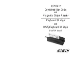
OMNI
Бренд: IDTECH Страницы: 33

MS842RP
Бренд: Unitech Страницы: 2


