Proximity Sensors Technical Guide
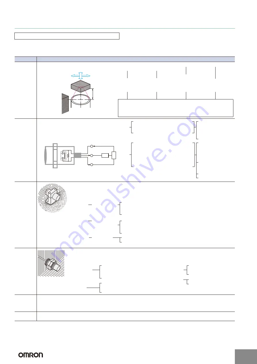
The following conditions must be considered to understand the conditions of the application and location as well as the relation to control
equipment.
●
Model Selection
* mT (millitesla) is a unit for expressing magnetic flux density. One tesla is the equivalent of 10,000 gauss.
Precautions for Correct Use
Item
Points of consideration
Sensing
object and
operating
condition of
Proximity
Sensor
Electrical
conditions
Environ-
mental
conditions
Mounting
conditions
Influence of
external
electromag-
netic fields
•
The influence within a DC magnetic field is 20 mT
*
max. Do not use the Sensor at a level higher than 20 mT.
•
Sudden changes in the DC magnetic field may cause malfunction. Do not use the Sensor for applications that involve turning a
DC electromagnet ON and OFF.
•
Do not place a transceiver near the Sensor or its wiring. Doing so may cause malfunction.
Other con-
siderations
Cost feasibility: Price/delivery time
Life: Power-ON time/frequency of use
Check the relation between the sensing object
and the Proximity Sensor.
Sensing object
Proximity Sensor
Sensing
distance
Surrounding
metals
Specific condi-
tions of object
Direction of ob-
ject movement
Peripheral metal
Sensing distance
Material, size,
shape, existence
of plating, etc.
Transit interval,
speed, existence
of vibration, etc.
Material, distance
to Sensor, orien-
tation, etc.
Fluctuation in tran-
sit point, allowable
error, etc.
Sensing (set) distance, shape of Sensor (rectangular, cylindrical, through-
beam, grooved), influence of peripheral metal (Shielded Sensors, Non-
shielded Sensors), response speed (response frequency), influence of
temperature, influence of voltage, etc.
Verify the electrical conditions of the control system
to be used and the electrical performance of the
Proximity Sensor.
Load
Output
Pro
ximity
Sensor
P
o
w
er
supply
Switching element
DC (voltage fluctuation, current ca-
pacity value)
AC (voltage fluctuation, frequency, etc.)
Need for S3D2 Controller
Power
supply
Selecting the power
supply type
DC
DC + S3D2 Controller
AC
{
Resistive load - Non-contact control system
Inductive load - Relay, solenoid, etc.
•
Steady-state current, inrush current
•
Operating, reset voltage (current)
Lamp load
•
Steady-state current, inrush current
Open/close frequency
Load
Selecting the power
supply type
DC
DC + S3D2 Controller
AC
Control output
Maximum current
(voltage)
Leakage current
Residual load voltage
{
The environmental tolerance of the Proximity Sensor
is better than that of other types of Sensors. However,
investigate carefully before using a Proximity Sensor
under harsh temperatures or in special atmospheres.
•
Water Resistance
Do not use the Sensor in water, rain, or outdoors.
•
Ambient Conditions
To maintain reliability of operation, do not use the
Sensor outside the specified temperature range or
outdoors. Even though the Proximity Sensor has a
water-resistant structure, it must be covered to pre-
vent direct contact with water or water-soluble cutting
oil. Do not use the Sensor in atmospheres with chem-
ical vapors, in particular, strong alkalis or acids (nitric
acid, chromic acid, or hot concentrated sulfuric acid).
•
Explosive Atmospheres
Do not use the Sensor in atmospheres where
there is a danger of explosion. Use an Explosion-
proof Sensor.
Temperature
and humidity
Highest or lowest
values, existence
of direct sunlight,
etc.
Temperature influence,
high-temperature use,
low temperature use,
need for shade, etc.
Atmosphere
Water, oil, iron
powder, or other
special chemicals
Need for water resis-
tance or oil resistance,
need for explosion-
proof structure
Vibration and
shock
Size, duration
Need for strength,
mounting method
When deciding the mounting method, take into consideration not
only restrictions due to mechanical devices, but also ease of main-
tenance and inspection, and interference between Sensors.
Wiring method,
existence of in-
ductance surges
Connection
Wires
Wire type, length, oil-resistant
cable, shielded cable, robot
cable, etc.
Conduits, ducts, pre-wired,
terminal wiring, ease of main-
tenance and inspection
Mounting procedure
Installation location
Existence of mounting
brackets, direct mounting,
secured with bolts or screws
Ease of maintenance and
inspection, mounting space
http://www.ia.omron.com/
C-2
(c)Copyright OMRON Corporation 2007 All Rights Reserved.


