Omron Sti H-T40M-P, Инструкция по установке и эксплуатации
"Omron Sti H-T40M-P - Продукт высокого качества с удобной установкой и эксплуатацией. Подробное руководство по установке и эксплуатации доступно для загрузки бесплатно на manualshive.com. Получите свое руководство сейчас и наслаждайтесь удобством использования этого устройства."
Поделиться
Скачать


Отзывы:
Нет отзывов
Похожие инструкции для Sti H-T40M-P
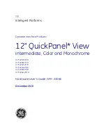
QuickPanel+ IC754VSI12CTD
Бренд: GE Страницы: 96
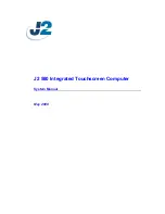
580
Бренд: J2 Страницы: 38
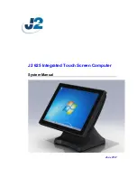
625
Бренд: J2 Страницы: 52
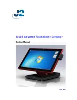
225
Бренд: J2 Страницы: 75
VERSA IC
Бренд: IBC Страницы: 10
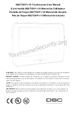
HS2TCHP
Бренд: NEO Страницы: 36
Frame
Бренд: TablerTV Страницы: 4
uEZ GUI
Бренд: FDI Страницы: 30

EntryLine UHD series
Бренд: Prowise Страницы: 54
Lightcloud Touch
Бренд: RAB Lighting Страницы: 10
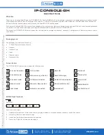
IP-CONSOLE-GH
Бренд: Atlas IED Страницы: 8
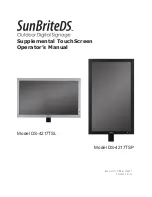
DS-4217TSL
Бренд: SunBriteDS Страницы: 4
DTH-1320
Бренд: Wacom Страницы: 11
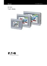
XV100
Бренд: Eaton Страницы: 80
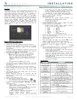
Equinox 73-II
Бренд: Vantage Hearth Страницы: 4
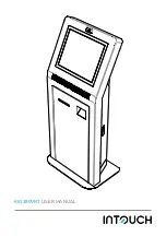
KIO190VRT
Бренд: InTouch Страницы: 4
DSC HS2TCHP
Бренд: Tyco Страницы: 132
CINTIQ DTK-2700
Бренд: Wacom Страницы: 27


