background image

4   Creating and Debugging the HMI Application

4 - 20

NA-series Programmable Terminal Startup Guide (V120)

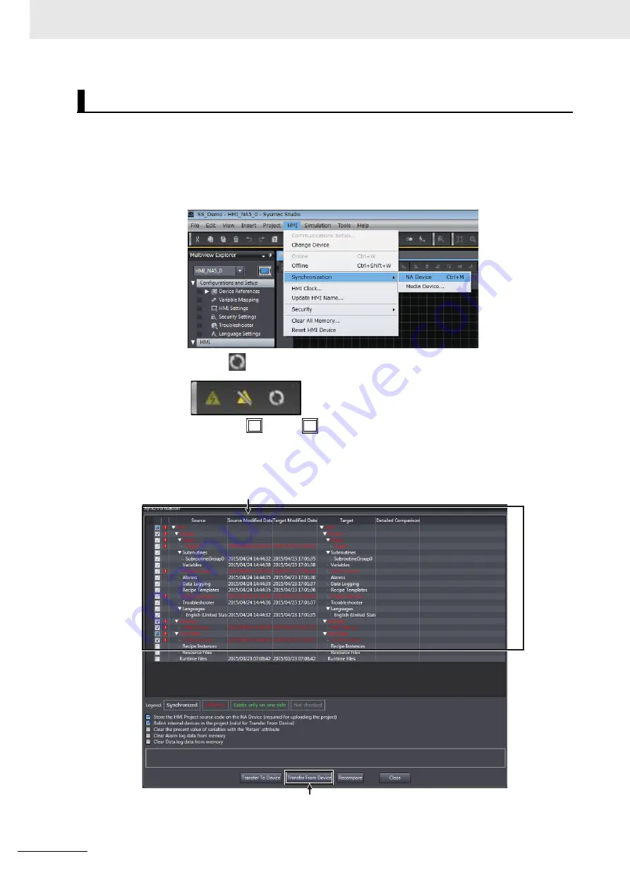
Use the following procedure to transfer the project to the HMI. Use synchronization to transfer the proj-
ect. You can use synchronization on the Sysmac Studio to automatically compare the data on the com-
puter with the data in the HMI and transfer data to the HMI.

1

Use one of the following methods to display the Synchronization Window.

Method 1: Select 

Synchronization - NA Device

 from the HMI Menu.

Method 2: Click 

 in the Toolbar.

Method 3: Press the 

 (Ctrl) + 

 (M) Keys.

Comparison of the data on the computer and the data in the HMI starts. When the comparison is 
completed, the comparison results are displayed.

Transferring the Project

Ctrl

M

The results of comparing the data on the computer and in the HMI are displayed.

Click this button to transfer the project from the computer to the HMI.

Содержание NA5-12*101 series

Страница 1: ...Programmable Terminal NA series Startup Guide V120 E1 03 NA5 15 101 NA5 12 101 NA5 9 001 NA5 7 001 ...

Страница 2: ...ation contained in this publication Sysmac and SYSMAC are trademarks or registered trademarks of OMRON Corporation in Japan and other countries for OMRON factory automation products Microsoft Windows Windows Vista Excel and Visual Basic are either registered trademarks or trademarks of Microsoft Corporation in the United States and other countries EtherCAT is registered trademark and patented tech...

Страница 3: ... place where it will be available for reference during operation This manual is intended for the following personnel who must also have knowledge of electrical sys tems an electrical engineer or the equivalent Personnel in charge of introducing FA systems Personnel in charge of designing FA systems Personnel in charge of installing and maintaining FA systems Personnel in charge of managing FA syst...

Страница 4: ...re User s Manual Cat No V117 NA series Programmable Terminal Software User s Manual Cat No V118 NA series Programmable Terminal Device Connection User s Manual Cat No V119 Operations are performed from the Sysmac Studio Automation Software Refer to the Sysmac Studio Version 1 Operation Manual Cat No W504 for information on the Sys mac Studio Other manuals are necessary for specific system configur...

Страница 5: ...m the front side of the panel Additional Information You can use an NS USBEXT 1M USB Relay Cable to extend the USB slave connector on the back panel of the NA series PT to the front surface of a control panel If you use the USB Relay Cable open a hole with the following dimensions and install the Cable 2 Attach the panel mounting brackets from the back of the panel as shown in the following figure...

Страница 6: ...of the product Precautions for Correct Use Indicates precautions on what to do and what not to do to ensure proper operation and perfor mance Additional Information Additional information to read as required This information is provided to increase understanding or make operation easier Version Information Information on differences in specifications and functionality with different versions is gi...

Страница 7: ... Programmable Terminal Startup Guide V120 1 2 3 4 5 4 3 2 1 Useful Functions I Index Creating and Debugging the HMI Application Preparations HMI Application Basics System Configurations and Startup Procedures 5 I Sections in this Manual ...

Страница 8: ...r Correct Use 16 Regulations and Standards 17 Related Manuals 19 Terminology 23 Revision History 24 Section 1 System Configurations and Startup Procedures 1 1 Startup Procedures 1 2 1 2 System Configurations and Units for Use 1 3 1 3 HMI Application to Create 1 4 Section 2 HMI Application Basics 2 1 Pages 2 2 2 2 Variables 2 3 2 3 Subroutines 2 4 Section 3 Preparations 3 1 Installing the Sysmac St...

Страница 9: ... 4 6 4 4 Adding the HMI to the Project 4 7 4 5 Mapping HMI Variables and Controller Variables 4 8 4 6 Making the Initial HMI Settings 4 10 4 7 Creating Pages 4 12 4 8 Debugging the HMI Application 4 18 4 8 1 Preparations for Online Debugging 4 18 4 8 2 Preparations for Offline Debugging 4 23 4 8 3 Debugging 4 24 Section 5 Useful Functions 5 1 Global Events 5 2 5 2 Protecting User Programming Asset...

Страница 10: ...CONTENTS 8 NA series Programmable Terminal Startup Guide V120 ...

Страница 11: ... price of the non complying Product provided that in no event shall Omron be responsible for warranty repair indemnity or any other claims or expenses regarding the Products unless Omron s analysis confirms that the Products were properly handled stored installed and maintained and not subject to contamination abuse misuse or inappropriate modification Return of any Products by Buyer must be appro...

Страница 12: ...esponsible for the user s programming of a programmable Product or any consequence thereof Data presented in Omron Company websites catalogs and other materials is provided as a guide for the user in determining suitability and does not constitute a warranty It may represent the result of Omron s test conditions and the user must correlate it to actual application requirements Actual perfor mance ...

Страница 13: ...dicates precautions on what to do and what not to do to ensure proper operation and performance Symbols The circle and slash symbol indicates operations that you must not do The specific operation is shown in the circle and explained in text This example indicates prohibiting disassembly The triangle symbol indicates precautions including warnings The specific operation is shown in the triangle an...

Страница 14: ...gn installation operation maintenance and disposal Ensure that installation and post installation checks are performed by personnel in charge who possess a thorough understanding of the machinery to be installed Do not use the input functions such as the touch panel or function keys of the NA Unit in applications that involve human life in applications that may result in serious injury or for emer...

Страница 15: ...l resistance will be lost if the front sheet is torn or is peeling off Do not use the NA Unit if the front sheet is torn or is peeling off As the rubber packing will deteriorate shrink or harden depending on the operating environment periodical inspection is necessary Confirm the safety of the system before turning ON or OFF the power supply or pressing the reset switch The whole system may stop d...

Страница 16: ...ontains a lithium primary battery with a perchlorate content of 6ppb or higher When exporting a product containing the NA Series to or shipping such a product through California USA label all packing and shipping containers appropriately Do not connect the USB devices in the environment subject to the strong vibration Do not connect USB devices which are not allowed to connect to NA Unit Start act...

Страница 17: ...ring or unreadable screen Additionally the bright ness can be restored by transferring the project again after setting the property of the brightness appropriately In a case of the applications where end users can control the brightness create the applications so as keeping on operations by such as assigning the function which restores the brightness to one of function keys if necessary Signals fr...

Страница 18: ...ect to corrosive or flammable gases Locations subject to strong shock or vibration Locations outdoors subject to direct wind and rain Locations subject to strong ultraviolet light Locations subject to dust Locations subject to direct sunlight Locations subject to splashing oil or chemicals Take appropriate and sufficient countermeasures when installing systems in the following locations Locations ...

Страница 19: ... EMS Electromagnetic Susceptibility EN 61131 2 2007 EMI Electromagnetic Interference EN 61131 2 2007 Conformance to EC Directives The NA series PTs comply with EC Directives To ensure that the machine or device in which the NA series PT is used complies with EC Directives the NA series PT must be installed as follows The NA Unit must be installed within a control panel You must use reinforced insu...

Страница 20: ...precaution if you use NA series PTs in Korea Class A Device Broadcasting Communications Device for Business Use This device obtained EMC registration for office use Class A and it is intended to be used in places other than homes Sellers and or users need to take note of this Conformance to KC Standards ...

Страница 21: ...es PT Information is provided on connec tion procedures and setting proce dures to connect an NA series PT to a Controller or other device NA series Program mable Terminal Startup Guide V120 NA5 W Learning in con crete terms infor mation required to install and start the operation of an NA series PT The part names and installation pro cedures are described followed by page creation and transfer pr...

Страница 22: ... settings Programming based on IEC 61131 3 language specifications Use this manual together with the NJ NX series CPU Unit Hardware User s Manual NJ Series W500 NX Series W535 CJ Series Program mable Controllers Operation Manual W393 CJ1H CPU H R CJ1G H CPU H CJ1G CPU P CJ1M CPU CJ1G CPU Learning the basic specifications of the CJ series PLCs including introductory infor mation designing installat...

Страница 23: ... mode commands and 2 FINS commands are described in detail Refer to this manual for information on communications commands C mode commands and FINS com mands addressed to CPU Units Note This manual describes com munications commands that are addressed to a CPU Unit The communications path is not relevant The communi cations commands can be sent through the serial com munications port of the CPU Un...

Страница 24: ...iving mail socket service automatic clock adjustment FTP server functions and FINS communications CS CJ series Ether Net IP Units Oper ation Manual W465 CJ2H CPU6 EIP CJ2M CPU3 CS1W EIP21 CJ1W EIP21 Learning how to use the built in EtherNet IP port of the CJ2 CPU Units Information is provided on the built in EtherNet IP port and EtherNet IP Units Basic settings tag data links FINS communications a...

Страница 25: ...t unless otherwise specified PT The hardware elements of the HMI NA Series The NA Series of Programmable Terminals and peripheral devices HMI Project A Sysmac Studio project for an HMI NA Unit An NA series Programmable Terminal Download Transferring data from the Sysmac Studio to an HMI IAG collection When you provide IAGs you provide them as IAG collections IAGs are also imported as IAG collectio...

Страница 26: ...al revision code appears as a suffix to the catalog number on the front and back covers of the manual Revision code Date Revised content 01 June 2014 Original production 02 October 2014 Corrected mistakes 03 October 2015 Made revisions accompanying version upgrade Cat No V120 E1 03 Revision code ...

Страница 27: ... the system configurations and the operation of the programming that is created for the startup procedures given in this guide 1 1 Startup Procedures 1 2 1 2 System Configurations and Units for Use 1 3 1 3 HMI Application to Create 1 4 System Configurations and Startup Procedures ...

Страница 28: ... System configuration Operations Sysmac Studio only Offline debugging The HMI application and user program for the Controller are created with the Sysmac Studio The operation of a virtual HMI and NJ series CPU Unit is simulated on the Sysmac Studio to debug the HMI applica tion Sysmac Studio NA series Programma ble Terminal CPU Unit Online debugging The HMI application and user program for the Con...

Страница 29: ...re Used Name Model Manual name NA series Programmable Terminal NA5 12W101B version 1 02 NA series Programmable Terminal Hardware User s Manual V117 Power Supply Unit S8VS Series NJ series CPU Unit NJ501 1500 version 1 01 NJ series CPU Unit Hardware User s Manual W500 NJ series Power Supply Unit NJ PA3001 Ethernet cable Commercially available Ethernet cable 1 1 Use a category 5 cable USB cable Comm...

Страница 30: ...meB Variable ControllerName_VariableNameC Green button lamp Page Yellow button lamp Red button lamp HMI Variable VariableNameA Variable VariableNameB Variable VariableNameC Controller Global Variables NJ series Controller These variables are mapped On the HMI page only the functions to control TRUE and FALSE at the Controller are implemented The buttons are transparent On the HMI page the function...

Страница 31: ...grammable Terminal Startup Guide V120 This section provides necessary basic knowledge of HMI applications for the NA series Programmable Terminals 2 1 Pages 2 2 2 2 Variables 2 3 2 3 Subroutines 2 4 HMI Application Basics ...

Страница 32: ...ble with conventional HMIs After you register a highly versatile subroutine as a global subroutine you can call the subroutine from anywhere in the project This improves reusability and maintainability Also the use of Visual Basic allows you to reuse any of the many samples that are available on the Internet to improve development productivity Attributes of pages and objects Description Properties...

Страница 33: ...al variable how ever can be read and written from everywhere in the project The application that is described in this guide defines the variables to access the pushbutton switches and lamps as global variables The data type is an attribute that defines the format and range of values that a variable can express When a variable is defined the data type must always be specified In an NA series Progra...

Страница 34: ...n Visual Basic You can create powerful appli cations by programming the processing to execute when events occur as subroutines There are the following two types of subroutines Type of subroutine Definition Page subroutine A subroutine that can be accessed only within one page Global subroutine A subroutine that can be accessed from anywhere in the project ...

Страница 35: ...s section describes how to install the Sysmac Studio and how to mount and wire the hardware 3 1 Installing the Sysmac Studio 3 2 3 2 Assembling the Hardware 3 3 3 2 1 Wiring the Power Supply 3 3 3 2 2 Connecting the Ethernet Communications Cable 3 4 Preparations ...

Страница 36: ...up Wizard 4 When the installation is completed restart the computer Additional Information The system requirements for the computer on which to install the Sysmac Studio are given in the following table If the Sysmac Studio cannot be installed with the above procedure refer to the Sysmac Stu dio Version 1 Operation Manual W504 Precautions for Correct Use If CX One version 4 or lower is installed o...

Страница 37: ... Assembling a panel Setting DIP switches Connecting and wiring cables Connecting or disconnecting connectors After you turn OFF the power supply the Power Supply Unit may continue to supply power to the NA Unit for several seconds The RUN indicator will remain lit as long as power is supplied Make sure that the RUN indicator is not lit before you perform any of the above operations Wire the power ...

Страница 38: ...al Startup Guide V120 Connect the Ethernet port and the Ethernet cable as shown in the following figure 3 2 2 Connecting the Ethernet Communications Cable Ethernet port Connect the cable to Ethernet port 1 Built in Ethernet port Communications cable ...

Страница 39: ...ting a New Project 4 3 4 3 Creating the HMI Application 4 6 4 4 Adding the HMI to the Project 4 7 4 5 Mapping HMI Variables and Controller Variables 4 8 4 6 Making the Initial HMI Settings 4 10 4 7 Creating Pages 4 12 4 8 Debugging the HMI Application 4 18 4 8 1 Preparations for Online Debugging 4 18 4 8 2 Preparations for Offline Debugging 4 23 4 8 3 Debugging 4 24 Creating and Debugging the HMI ...

Страница 40: ...ide describes the operating procedures to create the HMI application without connecting to the actual hard ware STEP 1 Creating a New Project P 4 3 A project file is created and the HMI is inserted into the project STEP 2 Making the Software Settings and Creating the HMI Application P 4 6 STEP 2 1 Software Settings Variable Mapping and HMI Settings P 4 8 STEP 2 2 Creating the HMI Application Regis...

Страница 41: ...he NJ series Machine Automation Controller Startup Guide CPU Unit W513 Use the following procedure to start the Sysmac Studio 1 Use one of the following methods to start the Sysmac Studio Double click the Sysmac Studio shortcut icon on the desktop Select All programs OMRON Sysmac Studio Sysmac Studio from the Windows Start Menu The Sysmac Studio is started and the following window is displayed Sta...

Страница 42: ... project that was created in the NJ series Machine Automation Controller Startup Guide CPU Unit W513 in the Project List Dialog Box and click the Open Button Click the Button Additional Information If you open a project that was created on a version of the Sysmac Studio that is older than ver sion 1 13 the following dialog box will be displayed Click the OK Button and convert the proj ect so that ...

Страница 43: ...4 5 4 Creating and Debugging the HMI Application NA series Programmable Terminal Startup Guide V120 4 2 Creating a New Project 4 The following window is displayed ...

Страница 44: ...asic color ON color OFF color Specified variable in Controller Bit Lamp objects Green LightGreen DarkGreen new_Controller_0_SwGreen Yellow Yellow Goldenrod new_Controller_0_SwYellow Red Red Firebrick new_Controller_0_SwRed Momentary Button objects Green Transparent Transparent new_Controller_0_SwGreen Yellow Transparent Transparent new_Controller_0_SwYellow Red Transparent Transparent new_Controll...

Страница 45: ...de V120 4 4 Adding the HMI to the Project 4 4 4 Adding the HMI to the Project Use the following procedure to add the HMI to the project 1 Select HMI NA5 from the Insert Menu 2 Select NA5 12W101 for the device and 1 02 for the version and then click the OK Button The HMI is added to the project ...

Страница 46: ...t click Variable Mapping under Configurations and Setup in the Multiview Explorer and select Edit from the menu 2 Right click User Variables under new_Controller_0 and select Create Device Variable from the menu HMI Global Variables Variable new_Controller_0_SwGreen Variable new_Controller_0_SwYellow Variable new_Controller_0_SwRed Green button lamp Page0 Yellow button lamp Red button lamp Variabl...

Страница 47: ... Debugging the HMI Application NA series Programmable Terminal Startup Guide V120 4 5 Mapping HMI Variables and Controller Variables 4 The Controller global variables are automatically mapped to the HMI global variables ...

Страница 48: ...d Startup Language Startup language Sets the project language to use when the HMI is started USB Keyboard Key layout Sets the layout of a USB keyboard Security Automatically log out user after period of inactivity Select this check box to automatically log out the user after a specified period of inactivity Inactivity period Specifies the time of inactivity before the user is logged out automatica...

Страница 49: ...of the primary WINS server Secondary WINS server Sets the IP address of the secondary WINS server Ethernet Port 2 Settings Direct connection with Sysmac Studio Select this check box to connect Ethernet port 2 directly to the Sysmac Studio without going through an Ethernet switch If you select this check box the IP addresses and other settings for Ethernet port 2 are ignored IP Address Sets the loc...

Страница 50: ...the Multiview Explorer Or right click Page0 under HMI Pages and select Edit from the menu HMI Global Variables Variable new_Controller_0_SwGreen Variable new_Controller_0_SwYellow Variable new_Controller_0_SwRed Green button lamp Yellow button lamp Red button lamp Each button lamp is implemented with a colored Bit Lamp object and a transparent Button object The following settings are made Bit Lamp...

Страница 51: ...Terminal Startup Guide V120 4 7 Creating Pages 4 2 Overlay a Momentary Button object on a Bit Lamp object to implement the actual button Click Lamps in the Toolbox and then drag a Bit Lamp object to the page 3 Set the properties of the Bit Lamp object Double click the object ...

Страница 52: ... Set Appearance LampColorOff to DarkGreen in the properties Also set LampColorOn to LightGreen 5 Assign a variable to the object Set Behavior Expression in the properties to new_Controller_0_SwGreen 6 Use the same steps to create the red and yellow lamps The settings are shown below Yellow Lamp Red Lamp ...

Страница 53: ...tons in the Toolbox and then drag a Momentary Button object to the page and overlay it on the Bit Lamp object 8 Match the size of the Momentary Button object with the size of the Bit Lamp object 9 Click the Momentary Button object Delete the setting of Appearance TextButtonUp Default Also delete the setting of TextButtonDown Default ...

Страница 54: ...d Color Tab under Appearance BackgroundColorButtonUp and select Transparent Set BackgroundColorButtonDown BorderColorButtonUp and BorderColorButtonDown in the same way 11 Assign a variable to the Momentary Button object Set Behavior Variable in the properties to new_Controller_0_SwGreen 12 Create buttons for the red and yellow lamps in the same way The settings are shown below Yellow Button ...

Страница 55: ...4 17 4 Creating and Debugging the HMI Application NA series Programmable Terminal Startup Guide V120 4 7 Creating Pages 4 Red Button This concludes creating the page ...

Страница 56: ...tly or connect to the Controller Simulator to verify operation Additional Information If you verify operation only with the HMI Simulator you can check the operation of objects but there is no way to verify operation according to values in the Controller To debug the operation for values in the Controller you must connect to the Controller Simulator Use the following procedure to build the project...

Страница 57: ...1 Turn ON the power supply to the HMI 2 Go online with one of the following methods Method 1 Select Online from the HMI Menu Method 2 Click in the Toolbar Method 3 Press the Ctrl W Keys The Sysmac Studio goes online with the HMI Going Online Ctrl W When the Sysmac Studio goes online the color of the bar at the top of the Edit Pane changes to yellow The HMI status is displayed ...

Страница 58: ...transfer data to the HMI 1 Use one of the following methods to display the Synchronization Window Method 1 Select Synchronization NA Device from the HMI Menu Method 2 Click in the Toolbar Method 3 Press the Ctrl M Keys Comparison of the data on the computer and the data in the HMI starts When the comparison is completed the comparison results are displayed Transferring the Project Ctrl M The resul...

Страница 59: ...bugging the HMI Application 4 4 8 1 Preparations for Online Debugging 2 Click the Transfer to Device Button Click the Button Transferring the project to the HMI starts During the transfer progress is displayed in the Syn chronization Window 3 When the transfer is completed the HMI is restarted automatically ...

Страница 60: ...pplication 4 22 NA series Programmable Terminal Startup Guide V120 4 Click the Close Button at the bottom right of the Synchronization Window Click the Button The Synchronization Window is closed 5 Check the operations on the actual HMI ...

Страница 61: ... procedures to build the project and start the HMI Simulator 1 Select Build HMI from the Project Menu The results of building the project are displayed in the Build Tab Page If any errors are found correct the project 1 Select Start NA Simulation from the Simulation Menu The Simulation Window is displayed This concludes starting the Simulator 4 8 2 Preparations for Offline Debugging Building the P...

Страница 62: ...Use the following procedure to debug the project that you created to ensure that it operates correctly Use the Simulator to click each button to confirm whether values are set in the Controller correctly and lamps are displayed correctly 1 Change the device to the Controller 2 Click Global Variables under Programming Data to open the Global Variables Tab Page and drag SwGreen SwRed and SwYellow to...

Страница 63: ...g and Debugging the HMI Application NA series Programmable Terminal Startup Guide V120 4 8 Debugging the HMI Application 4 4 8 3 Debugging 3 Select Run with NA Simulator from the Simulation Menu 4 Click the OK Button ...

Страница 64: ...26 NA series Programmable Terminal Startup Guide V120 5 Confirm that the values of the Controller variables change when you press the buttons on the page In the same way confirm that changes to the values on the Watch Tab Page are shown on the page ...

Страница 65: ... Terminal Startup Guide V120 This section describes useful functions that you can use with an NA series Program mable Terminal and the Sysmac Studio 5 1 Global Events 5 2 5 2 Protecting User Programming Assets 5 5 Useful Functions ...

Страница 66: ...onitor the value of a device and for example display a specific page when the value of a device reaches a specified value or you can specify the operation to perform when a function key is pressed This section describes an example to implement the function of a green button with a function key 1 Double click Global Event under HMI in the Multiview Explorer Or right click Global Event under HMI and...

Страница 67: ... Functions NA series Programmable Terminal Startup Guide V120 5 1 Global Events 5 3 Select SetVariable from Actions 4 Set Variable to new_Controller_0_SwGreen and set Value to True 5 Select F1KeyRelease from Events ...

Страница 68: ...5 Useful Functions 5 4 NA series Programmable Terminal Startup Guide V120 6 Select SetVariable from Actions 7 Set Variable to new_Controller_0_SwGreen and set Value to False ...

Страница 69: ...ed This section provides an overview of the security functions Additional Information For the details on security refer to the Sysmac Studio Version 1 Operation Manual W504 and NA series Programmable Terminal Software User s Manual V118 Security function Purpose Overall project file protection Preventing the theft of assets Operation authority verification Preventing incorrect operation Write prot...

Страница 70: ...5 Useful Functions 5 6 NA series Programmable Terminal Startup Guide V120 ...

Страница 71: ...I 1 I NA series Programmable Terminal Startup Guide V120 Index ...

Страница 72: ... event driven applications 2 2 events and actions 2 2 G global events 5 2 global subroutines 2 4 global variables 2 3 I initial settings 4 10 installing the Sysmac Studio 3 2 M mapping 4 8 O offline debugging 1 2 4 23 online debugging 1 2 4 18 P page subroutines 2 4 properties 2 2 S security function 5 5 startup procedures 1 2 subroutine variables 2 3 subroutines 2 4 system configuration 1 3 V var...

Страница 73: ......

Страница 74: ... 60169 U S A Tel 1 847 843 7900 Fax 1 847 843 7787 Regional Headquarters OMRON EUROPE B V Wegalaan 67 69 2132 JD Hoofddorp The Netherlands Tel 31 2356 81 300 Fax 31 2356 81 388 Contact www ia omron com Kyoto JAPAN OMRON ASIA PACIFIC PTE LTD No 438A Alexandra Road 05 05 08 Lobby 2 Alexandra Technopark Singapore 119967 Tel 65 6835 3011 Fax 65 6835 2711 OMRON CHINA CO LTD Room 2211 Bank of China Towe...

Отзывы: