background image

Installation

FQ Short Manual

 2

In

sta
llatio

n

 a

nd 

Con

nection

s

13

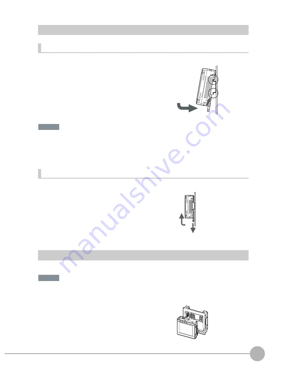
Mounting to DIN Track

Installation Procedure

• Attach End Plates (sold separately) on the sides of the Touch Finder on the DIN Track.

• If other devices will be installed next to the Touch Finder on the same DIN Track, make sure that sufficient space is

kept between the devices as indicated on previous page.

• Always hook the clip at the top of the Touch Finder on the DIN Track first. If the lower clip is hooked on first, the

Touch Finder will not be mounted very securely.

Removal Procedure

Mounting to a Control Panel

The Touch Finder can be mounted on a panel using the FQ-XPM Panel Mounting Adapter.

• Always turn OFF the Touch Finder power before attaching or detaching the Panel Mount Adapter. Attaching or

detaching with the power turned ON may cause a failure.

1

Press the slider on the Touch Finder to the top. 

2

Hook the clip at the top of the Touch Finder on to the DIN

Track.

3

Press the Touch Finder onto the DIN Track until the bottom

clip clicks into place. 

1

Pull down on the slider on the Touch Finder.

2

Lift the Touch Finder at the bottom and remove it from the

DIN Track.

1

Set the Touch Finder in the Panel Mount Adapter.

1

2

3

3

Important

2

1

Important

Содержание FQ

Страница 1: ...Short Manual Vision Sensor FQ Cat No Z306 E1 01 ...

Страница 2: ...ty 25 3 3 Adjusting the Object Position 30 4 Setting Up Inspections 4 1 Inspection Item Selection Guide 34 4 2 Setup Procedure for Inspection Items 35 4 3 Inspecting with the Search Inspection Item 36 4 4 Inspecting with the Edge Position Inspection Item 38 4 5 Inspecting with the Edge Width Inspection Item 40 4 6 Inspecting with the Area Inspection Item 42 4 7 Inspecting with Color Data Inspectio...

Страница 3: ...isplay 56 6 3 Adjusting Judgement Parameters during Operation 58 7 Communications with External Devices 7 1 Operation with Default Configuration 60 7 2 Setting the Measurement Trigger 61 7 3 Setting the Outputs 65 7 4 Controlling the Sensor from an External Device 68 Revision History 74 ...

Страница 4: ...1 Introduction Introduction 1 1 FQ series Vision Sensors 4 1 2 Measurement Process 5 1 3 Startup Display and Display Elements 6 1 4 Basic Operational Flow 8 ...

Страница 5: ...del Single function model Model number FQ S2 FQ S1 Number of simultaneous measurements 32 1 Number of registered scenes 32 8 Position compensation Supported Not supported The same functions as those that are provided by the Touch Finder can be performed from a computer The PC Tool is available free of charge Includes the camera lighting measurement processor and I O functions After the Sensor has ...

Страница 6: ...ng a trigger signal from an external device Images are taken according to the trigger The image is measured to see if it matches the configured settings The overall judgement of all inspection items are output using OR logic Measurement data and image data can be logged in memory in the Sensor or in an SD card Trigger input Take image Measurement Overall judgement output Logging ...

Страница 7: ... that cables are connected cor rectly to the Sensor and Touch Finder and then press Auto connect 2 When the Sensor is detected the following display will appear The Setup Mode will appear if a Sensor that has not been set up is connected The Run Mode will appear if a Sensor that has been set up is connected When the Touch Finder is started IP addresses are automatically set for each Sensor To allo...

Страница 8: ...ect scenes Capture Button Used to capture the current screen to the SD card This button menu is always displayed Image Used to adjust the image In Out Used to set the I O Run Used to switch to Run Mode Test Used to test and adjust the set measurements Inspect Used to set the inspection items The setup flow is shown by these five tabs If the Button appears pressing it will display the sub menu or c...

Страница 9: ... Settings Adjusting Judgement Parameters Test Measurement and Results Verification Testing Test Tab Page Output Settings In Out Tab Page Setup Evaluation 1 Setting Judgement Parameters Inspection Setup Inspect Tab Page Teaching Registering Inspection Items Image Setup Image Tab Page Starting the Sensor Connections and Wiring Section 2 Installation and Connections Section 1 1 3 Startup Display and ...

Страница 10: ...2 Installation and Connections Installation and Connections 2 1 System Configuration 10 2 2 Installation 11 2 3 Wiring 15 2 4 Setting Up Ethernet 20 ...

Страница 11: ...gistra tion procedure and the download procedure for spe cial member software FQ Ethernet Cable FQ WN0 Connects the Sensor to the Touch Finder or com puter Standard RJ45 Ethernet Cable Connects the switching hub to the Touch Finder or computer STP shielded twisted pair cable cate gory 5e or 6 impedance 100 Ω I O Cable FQ WD0 Connects the Sensor to the power supply and exter nal devices Switching H...

Страница 12: ...m Mounting Bracket 6 8 10 12 14 0 20 40 60 50 130 210 0 100 200 300 35 45 55 200 600 1 000 200 400 0 0 400 Horizontal field of view mm Horizontal field of view mm Installation distance L mm Installation distance L mm FQ S10050F FQ S15050F FQ S20050F or FQ S25050F FQ S10100N FQ S15100N FQ S20100N or FQ S25100N Horizontal field of view mm Horizontal field of view mm Installation distance L mm Instal...

Страница 13: ...of the Touch Finder The distance between the Touch Finder and other devices should be at least that shown in the following diagram Make sure that the ambient temperature is 50 C or lower If it exceeds 50 C install an cooling fan or an air condi tioner and maintain the temperature at 50 C or lower To prevent interference by noise do not mount the Sensor on panels which contain high voltage devices ...

Страница 14: ...unted very securely Removal Procedure Mounting to a Control Panel The Touch Finder can be mounted on a panel using the FQ XPM Panel Mounting Adapter Always turn OFF the Touch Finder power before attaching or detaching the Panel Mount Adapter Attaching or detaching with the power turned ON may cause a failure 1 Press the slider on the Touch Finder to the top 2 Hook the clip at the top of the Touch ...

Страница 15: ... cable to the Touch Finder 5 Mount the Touch Finder with the Panel Mount Adapter from the front of the panel 6 Hook the hooks on the Mounting Bracket in the four holes of the Panel Mount Adapter and secure them with screws Tightening torque 1 2 N m 7 Check that the Touch Finder is attached properly to the Panel Mounting Bracket ...

Страница 16: ...c induction may cause the Sensor to malfunction or may damage it GND Inputs TRIG This terminal is the trigger signal input IN0 to IN5 These are the command input terminals Outputs OUT0 OR By default this is the OR output signal overall judgement The assignment can be changed to an individual judgement signal from OR0 to OR31 OUT1 BUSY By default this is the BUSY output signal The assignment can be...

Страница 17: ...system use a UL Class II DC power supply Attaching the LED Warning Label Attach the enclosed LED warning label to the cable or other location The LED warning label must be attached to a location that is readily visible from the Sensor Item Description Power supply voltage 24 VDC 21 6 to 26 4 V Output current 3 75 A min Recommended Power Supply S8VS 09024 24 VDC 3 75 A External power supply termina...

Страница 18: ...rminal screws using a Phillips screwdriver 2 Attach crimp terminals to the power lines Secure the positive and negative lines as indicated using M3 screws Power supply tightening torque 0 54 N m 3 In environments where there is excessive noise at tach a ferrite core ZCAT1730 0730 from TDK or the equivalent to the power supply cable 1 Remove the cover from the power switch on the left side of the T...

Страница 19: ...ery cover 2 Face the rounded side of the battery toward the back of the Touch Finder and insert the battery Do not insert the battery in the wrong orientation 3 Close the battery cover slide the battery cover in the direc tion of the arrow and tighten the screw on the battery cov er 4 Attach the AC adapter to the Touch Finder to start changing the battery The CHARGE indicator will be lit while the...

Страница 20: ... the protective circuit may activate and stop the Touch Finder The battery complies with the following recycling regulation California regulations concerning perchlorate This product is a lithium battery that contains perchlorate which is regulated by the State of California Please com ply with these regulations For details see the following URL www dtsc ca gov hazardouswaste perchlorate Important...

Страница 21: ...according to the network settings Touch Finder Setup Mode TF settings Ethernet 1 Set the IP address and subnet mask according to the network settings Connecting to Sensors from a Computer Using the PC Tool When connecting the Sensor directly to a computer using an Ethernet Cable set the network settings on the computer as given below Setting a fixed IP address is not required if there is a hub bet...

Страница 22: ... 21 4 On the General Tab Page double click Internet Proto col TCP IC 5 Select the Use the following IP address Option and en ter the following IP address and subnet mask IP address 10 5 5 101 Subnet mask 255 255 255 0 6 Click the OK Button This completes the settings ...

Страница 23: ...Setting Up Ethernet 22 FQ Short Manual MEMO ...

Страница 24: ...3 Taking Images Taking Images 3 1 Selecting a Sensor for Configuration 24 3 2 Adjusting Image Quality 25 3 3 Adjusting the Object Position 30 ...

Страница 25: ...ngle Touch Finder or computer you can select the Sensor that you want to set up 1 Press Run This will enable setting the current Sensor into RUN Mode before selecting another Sensor 2 Then press Switch to Run mode 3 Press Yes 4 Press Switch Sensor 5 Select the Sensor to be set up 6 Press Sensor settings to return to Setup Mode 7 Press Yes ...

Страница 26: ...is greater than 0 1 N m This may damage it 1 Display the Camera Setup Display The focus can be seen as a numerical value The higher the value the better the focus 2 Manually adjust the focus using the focus adjust ment screw on the Sensor while checking the image and focus value on the Touch Finder In the default settings the field of view is set to the nar rowest setting 3 Press Back Focus Level ...

Страница 27: ...lurring can be reduced by decreasing the exposure time Image Camera setup Brightness Adjusting the Brightness p 26 The image becomes darker the smaller the exposure time If the Sensor is used in a dark environment make sure that the darkness of the image does not cause the measurements to be unstable 1 Press Brightness on the right side of the dis play 2 Move the bar to the left or right to adjust...

Страница 28: ...he HDR function combines several images of different brightnesses exposure times so that the resulting image has a lower degree of contrast and can be measured stably for the desired characteristic Function Description HDR High Dynamic Range If objects have contrasting light and dark areas the dynamic range can be made wider to improve the quality of the images Polarizing filter Specular reflectio...

Страница 29: ...ilter is used If the image becomes too dark adjust the brightness p 26 Mounting the Filter 1 Press Brightness on the right side of the display 2 Press the HDR ON Button The best HDR mode will be selected automatically The enabled range will appear in blue on the brightness adjust ment bar 3 Press the OK Button If the measurement object is changed after setting the HDR function press the AUTO Butto...

Страница 30: ...uilt in to the Sensor is used the white balance is already adjusted No setting is required in this case Image Camera setup 2 Using the top section as a pivot point pull down the filter so that it attaches to the Sensor 1 Input a picture of white paper or cloth 2 Press White balance on the right side of the display 3 Press the Auto Button The Sensor will automatical ly adjust the colors 4 Move the ...

Страница 31: ...o that the object to be measured is moved exactly to the measurement region Image Position compensation Mode on off Function Description Reference Position compensation If the timing of the trigger is accurate the FQ Vision Sensor can correct variations in the position of the object for each measurement with the Position Compensation function p 30 Trigger delay A delay can be applied from when the...

Страница 32: ...he center 5 Press Model region 6 Move the rectangle so that the characteristic part for position compensation is inside it 7 Press OK 8 Press Teach The characteristic part and reference position for position compensation will be registered 9 Press OK to save the settings Drag a corner to size the rectangle Drag the rectangle to move it ...

Страница 33: ...ries in the image the Position Compensation function must also be used Image Trigger setup Trigger delay 1 A TRIG signal is input Images are input continuously 2 Select the image with the measurement object in the center using and 3 Press the image 4 Press OK The delay time can be set using the adjustment bar or by directly entering a value Trigger input Sensor Delay from when the trigger is input...

Страница 34: ...up Procedure for Inspection Items 35 4 3 Inspecting with the Search Inspection Item 36 4 4 Inspecting with the Edge Position Inspection Item 38 4 5 Inspecting with the Edge Width Inspection Item 40 4 6 Inspecting with the Area Inspection Item 42 4 7 Inspecting with Color Data Inspection Item 44 ...

Страница 35: ...are being judged Inspection Example Inspection items used Refer ence Judging according to shapes Judging if there is a mark Search p 36 Judging according to positions Measuring the position offset of a seal Edge Posi tion p 38 Judging according to widths Measuring the width between lead wires Edge Width p 40 Judging according to sizes Judging if there is silver paste Area p 42 Judging according to...

Страница 36: ...on items are shown below If measurements are unstable Only one inspection item can be used with a single function model FQ S1 Sensors Up to 32 inspection items can be combined and used with a standard model FQ S2 Sensors Step 3 Step 2 Step 1 Setting Judgement Parameters Teaching Configuring Inspection Items Step 5 Step 4 Re teaching Setting Detailed Items Note ...

Страница 37: ...e pattern is present or if the shape is different The image pattern that is registered in advance is called the model The degree to which the image matches the model is called the correlation Setup Procedure for the Search Inspection Item Step 1 Selecting the Inspection Item Inspect 1 Press an unused inspection item number and press Add item 2 Press Search OK NG Search region region to search for ...

Страница 38: ...ttings will be registered when teaching has been completed 6 Press Back to end teaching Item Parameter Description Reference data Model image This is the partial image that is stored as the reference Reference position X These are coordinates of the model image that are stored as reference Reference position Y 1 Press Judgement 2 Set the correlation range for an OK judgement Continuous measurement...

Страница 39: ...roduct is set in the correct position Places where the color changes greatly are called edges The positions of these edges are measured Setup Procedure for Edge Position Step 1 Selecting the Inspection Item Inspect 1 Press an unused inspection item number and press Add item 2 Press Edge position OK NG Edge search direction Color of edge to be found Measurement region An edge is detected within the...

Страница 40: ...ompleted 6 Press Back to end teaching Item Parameter Description Reference data Reference position X The reference coordinates X Y of the position are set automatically Reference position Y 1 Press Judgement 2 Set the range within which the D Position is judged as OK Continuous measurements will be performed for the im ages that are displayed 3 Press OK to enter the value Item Parameter Setting De...

Страница 41: ...r changes greatly are called edges The distance between two edges is called the edge width Setup Procedure for Edge Width Inspection Item Step 1 Selecting the Inspection Item Inspect 1 Press an unused inspection item number and press Add item 2 Press Edge Width OK NG Color of edge to be found Measurement region Edges are searched from two directions and the distance is calculated Sample Settings S...

Страница 42: ...ic settings will be registered when teaching has been completed 6 Press Back to end teaching Item Parameter Description Reference data Reference width The reference edge width is set automatically 1 Press Judgement 2 Set the D Width range for an OK judgement Continuous measurements will be performed for the im ages that are displayed 3 Press OK to enter the value Item Parameter Setting Description...

Страница 43: ...f a color within the measurement region The size is calculated as a number of pixels and it is called the area Setup Procedure for Area Step 1 Selecting the Inspection Item Inspect 1 Press an unused inspection item number and press Add item 2 Press Area OK NG Judges according to the number of pixels area of the specified color Specified color Measurement region Sample Settings Sample Measurement ...

Страница 44: ...gistered when teaching has been completed 6 Press Back to end teaching Item Parameter Description Reference data Extract color If the extract color has not been set the target color will be automatically extracted Reference area The area to use as a reference is set automatically 1 Press Judgement 2 Set the D Area range for an OK judgement Continuous measurements will be performed for the im ages ...

Страница 45: ...set for a portion of the image with the color that is to be measured This region is called the measurement region The average color within the measurement region is measured Setup Procedure for Color Data Inspection Item Step 1 Selecting the Inspection Item Inspect 1 Press an unused inspection item number and press Add item 2 Press Color Data OK NG Measurement region Judges using the average color...

Страница 46: ...istered when teaching has been completed 6 Press Back to end teaching Item Parameter Description Reference data Hue The hue to use as a reference is set automatically Saturation The saturation to use as a reference is set automatically Brightness The brightness to use as a reference is set automatically 1 Press Judgement 2 Set the range of color differences that are to be judged as OK Continuous m...

Страница 47: ...Inspecting with Color Data Inspection Item 46 FQ Short Manual MEMO ...

Страница 48: ...and Saving Settings Testing and Saving Settings 5 1 Performing Test Measurements 48 5 2 Adjusting the Judgement Parameters 49 5 3 Checking a List of All Inspection Item Results 51 5 4 Saving Data to the Sensor 52 ...

Страница 49: ...l judgement of all inspection items can be performed Test measurements can be performed for through images default or saved images Performing Test Measurements with Samples Test Continuous test 1 Press Graphics Details 2 Input an image of a previously prepared object Check the judgement results 3 When you finish checking the results press Back The same five types of displays are available for the ...

Страница 50: ...n items can be automatically adjusted by using actual workpieces which are considered as good and faulty products Test Continuous test 1 Press Adjust judgement on the right of the display 2 Adjust the judgement parameters 1 Move to the inspection item for which you want to au tomatically adjust the judgement parameters and press Adjust judgement on the right side of the display 2 Press Auto adjust...

Страница 51: ...f the variations between OK object is used as the judgement condition 2 Threshold average The median value between the OK object variations and NG object variations is used as the judgement condition 3 Threshold maximum The upper limit of the variations between NG object is used as the judgement condition Note Measurement value Press OK Teach to register Press NG Teach to register Number of regist...

Страница 52: ... Individual judgement results for all inspection items can be checked in a list The individual inspection items can be selected to change the judgement parameters Test Continuous test 1 Press All results region to display the list Judgement parameters can also be changed from this display Select an inspection item and press Adjust judgement Note ...

Страница 53: ...ith a message if you switch from Setup Mode to Run Mode You can use this feature to keep the previous settings and discard the new settings if desired but keep in mind that all settings that are not saved explicitly are replaced by the settings that are stored in the memory of the FQ Vision Sensor the next time you turn ON the FQ Vision Sensor Do not turn the power supply OFF while data is being s...

Страница 54: ...6 Operation Operation 6 1 Starting Operation 54 6 2 Configuring the Run Mode Display 56 6 3 Adjusting Judgement Parameters during Operation 58 ...

Страница 55: ...owing ways Run Mode Display Moving to Run Mode You can move from Setup Mode to Run Mode by using the following procedure 1 Press Run 2 Press Switch to Run mode 3 Press Yes If you press No the setting will not be saved and you will move to Run Mode The present display name Overall judgement Measurement processing time The time taken from when an image is input until all measurements have been compl...

Страница 56: ...d press Sensor settings Signal Status When Moving to Run Mode When moving to Run Mode the signal will change as shown below and data can be input from and output to an external device Note ON OFF The BUSY signal that was always ON will turn OFF BUSY signal Display Run Mode Setup Mode ...

Страница 57: ...nt results and measurement values of selected inspection items will appear Statistical data The currently measured image and history of the overall judgement results measurement count NG count and NG rate will appear Checking the Judgements of All Inspec tion Items in a List Displaying Measurement Result Histories All results region Standard Models Only Trend monitor Histogram The judgement result...

Страница 58: ...Results You can scroll though the measurement results of all the configured inspection items by using the following operations The following are also displayed in addition to the measurement results for each inspection item Camera input The image that is being measured is displayed Position comp The result of position compensation is displayed All Region The measurement regions for all inspection ...

Страница 59: ...peration Turn ON the function if you want to use it Setup Mode Sensor settings Adjustment mode in Run 1 Press ON Changing the Judgement Parameters in Run Mode This section describes how to change the judgement parameters without stopping measurement in Run Mode Run Mode 1 Select the inspection item for which you want to ad just the judgement parameters using the and Buttons 2 Press Adjust judgemen...

Страница 60: ...th External Devices Communications with External Devices 7 1 Operation with Default Configuration 60 7 2 Setting the Measurement Trigger 61 7 3 Setting the Outputs 65 7 4 Controlling the Sensor from an External Device 68 ...

Страница 61: ...The following settings can be selected depending on the system configuration and application Type of change Change Reference Changing the type of measurement trigger Performing continuous measurements p 62 Changing the output method of the judgement results Obtaining individual judgement results p 66 2 Measurements performed 1 Measurement trigger input 3 Judgement results output Trigger Sensor FQ ...

Страница 62: ...SY signal is turned ON during the measurement process 3 When the measurement has been finished the measurement result is output using an OR signal and the BUSY signal is turned OFF 1 1 You can also set the signal to be turned OFF after data logging image logging or displaying results in the BUSY output Color Signal Description The signals shown at the left are used Refer to the following informati...

Страница 63: ...IN5 signals Signal Address Output signals OUT0 OR signal CIO 0 00 OUT1 BUSY signal CIO 0 01 Input signals TRIG CIO 1 00 This function can be used only when the input mode is set to Expanded Mode SET TRIG W0 00 OUT1 0000 2 TRIG TMHH RSET TRIG T0000 RSET W0 00 L 1000 L 1002 OUT0 OUT0 OUT1 Single measure ment command bit BUSY signal When the single measurement command bit W0 00 turns ON the TRIG sign...

Страница 64: ...at the left are used Refer to the following informa tion for signal wiring Wiring p 15 Gray IN0 OFF Command parameters for continu ous measurements Green IN1 OFF Red IN2 OFF White IN3 OFF Purple IN4 OFF Yellow IN5 ON Command input for continuous measurements Black OUT0 OR Overall judgement default assign ment Orange OUT1 BUSY Processing in progress default assignment OFF ON OFF ON OFF ON OR signal...

Страница 65: ... 0000 5 TMHH SET IN5 T0000 OUT1 W0 00 RSET W0 00 RSET IN5 W0 01 RSET W0 00 Continuous measurement command bit Continuous measurement command bit BUSY signal Continuous measurement stop bit When the continuous measurement command bit W0 00 turns ON the command parameter for continuous measurements 00000 is output to Q 1 IN0 to IN4 If the BUSY signal is OFF 5 ms after the command parameter is output...

Страница 66: ...ttings of the BUSY signal BUSY output conditions Color Signal Description The signals shown at the left are used Refer to the following information for signal wiring Black OUT0 OR Overall judgement default assignment 2 3 Wiring p 15 OK NG OK Inspection item 31 If there is even one NG judgement the overall judgement will be NG and the output will be turned ON NG OR signal ON Inspection item 1 Overa...

Страница 67: ...ssigned to individual judgement output signals the BUSY signal and ERROR signal assigned as the default settings will no longer be output Output terminal Output signals that can be assigned OUT0 OR Total judgement default OR0 Item 0 judgement to OR31 Item 31 judgement OUT1 BUSY default OR0 Item 0 judgement to OR31 Item 31 judgement OUT2 ERROR default OR0 Item 0 judgement to OR31 Item 31 judgement ...

Страница 68: ...t conditions Settings In Out I O setting Output 1 Press OUT0 2 Press OR2 Item 2 judgement OR2 output signal was assigned to OUT0 3 Assign the others in the following manner OUT1 OR5 OUT2 OR14 OFF ON OFF ON OR1 signal Turned ON when individual judgement is NG Output polarity ON for NG OR0 signal Turned ON when individual judgement is NG Output polarity ON for NG Example ON while measurements are be...

Страница 69: ...ment is performed while this command is input p 62 Color Signal State Description The signals shown at the left are used Refer to the following information for signal wiring 2 3 Wiring p 15 Input Mode Standard Mode Expanded Mode Gray IN0 Scene number 0 to 31 Scene number 0 to 15 Specifies the scene number Green IN1 Red IN2 White IN3 Purple IN4 ON Yellow IN5 ON Trigger to change the scene Orange OU...

Страница 70: ... Address Output signals OUT1 BUSY signal CIO 0 01 Input signals IN0 CIO 1 08 IN1 CIO 1 09 IN2 CIO 1 10 IN3 CIO 1 11 IN4 CIO 1 12 IN5 CIO 1 15 MOV 1100 Q 1 TMHH 0000 5 TMHH 0001 2 SET IN5 RSET IN5 SET W0 01 W0 00 T0000 IN5 OUT1 BUSY W0 00 RSET W0 00 T0001 BUSY Scene change bit Scene change bit When the scene change bit W0 00 turns ON the scene number is input to IN0 to IN3 and IN4 is turned ON If t...

Страница 71: ...ode Wiring Inspection item Re registered data Search Model data Color data Reference color hue saturation and brightness Edge Position Edge Width Area None Application is possibly only from the Run Mode If the parameter is applicable to more than one inspection item it will be re registered for all inspection items Color Signal State Description The signals shown at the left are used Refer to the ...

Страница 72: ...ng Start re registering BUSY signal IN5 signal ON for 1 ms min Allow 5 ms min and then turn ON IN5 IN0 to IN4 signals MOV 800 Q 1 TMHH 0000 5 TMHH 0001 2 SET IN5 RSET IN5 SET W0 01 W0 00 T0000 IN5 OUT1 BUSY W0 00 RSET W0 00 T0001 BUSY Model re register bit Model re register bit When the mode re register bit W0 00 turns ON IN3 is turned ON If the BUSY signal is OFF 5 ms after IN3 turns ON the comma...

Страница 73: ...is being re registered If the cycle time is too long the PLC may not be able to detect when the BUSY signal is ON If necessary turn OFF W0 00 after a suitable time elapses Signal Address Output signals OUT1 BUSY signal CIO 0 01 Input signals IN0 CIO 1 08 IN1 CIO 1 09 IN2 CIO 1 10 IN3 CIO 1 11 IN4 CIO 1 12 IN5 CIO 1 15 Note Important ...

Страница 74: ... I O setting Input Input mode Press Expand mode Wiring Timing Chart This function can be used in Run Mode only Color Signal State Description The signals shown at the left are used Refer to the following information for signal wiring 2 3 Wiring p 15 Gray IN0 OFF Command parameter for clearing errors Green IN1 OFF Red IN2 ON White IN3 OFF Purple IN4 OFF Yellow IN5 ON Command input for clearing erro...

Страница 75: ...story A manual revision code appears as a suffix to the catalog number at the bottom of the front and back covers of this manual Revision code Date Revised contents 01 August 2010 Original production Cat No Z306 E1 01 Revision code ...

Страница 76: ... U S A Tel 1 847 843 7900 Fax 1 847 843 7787 Regional Headquarters OMRON EUROPE B V Sensor Business Unit Carl Benz Str 4 D 71154 Nufringen Germany Tel 49 7032 811 0 Fax 49 7032 811 199 Contact www ia omron com Tokyo JAPAN OMRON ASIA PACIFIC PTE LTD No 438A Alexandra Road 05 05 08 Lobby 2 Alexandra Technopark Singapore 119967 Tel 65 6835 3011 Fax 65 6835 2711 OMRON CHINA CO LTD Room 2211 Bank of Ch...

Отзывы: