


Photoelectric Sensors Technical Guide
Noise
Countermeasures for noise depend on the path of noise entry, frequency components, and wave heights. Typical measures are as given in the
following table.
●
Wiring
Cable
Unless otherwise indicated, the maximum length of cable extension is
100 m using wire that is 0.3 mm
2
or greater.
Exceptions are indicated in
Safety Precautions
in individual product
information.
Cable Tensile Strength
When wiring the cable, do not subject the cable to a tension greater than
that indicated in the following table.
Note: Do not subject a shielded cable or coaxial cable to tension.
Repeated Bending
Normally, the Sensor cable should not be bent repeatedly.
(For bending-resistant cable, see
Attachment to Moving Parts
on
page
C-
4
.)
Separation from High Voltage (Wiring Method)
Do not lay the cables for the Sensor together with high-voltage lines
or power lines. Placing them in the same conduit or duct may cause
damage or malfunction due to induction interference. As a general
rule, wire the Sensor in a separate system, use an independent metal
conduit, or use shielded cable.
Work Required for Unconnected Leads
Unused leads for self-diagnosis outputs or other special functions
should be cut and wrapped with insulating tape to prevent contact with
other terminals.
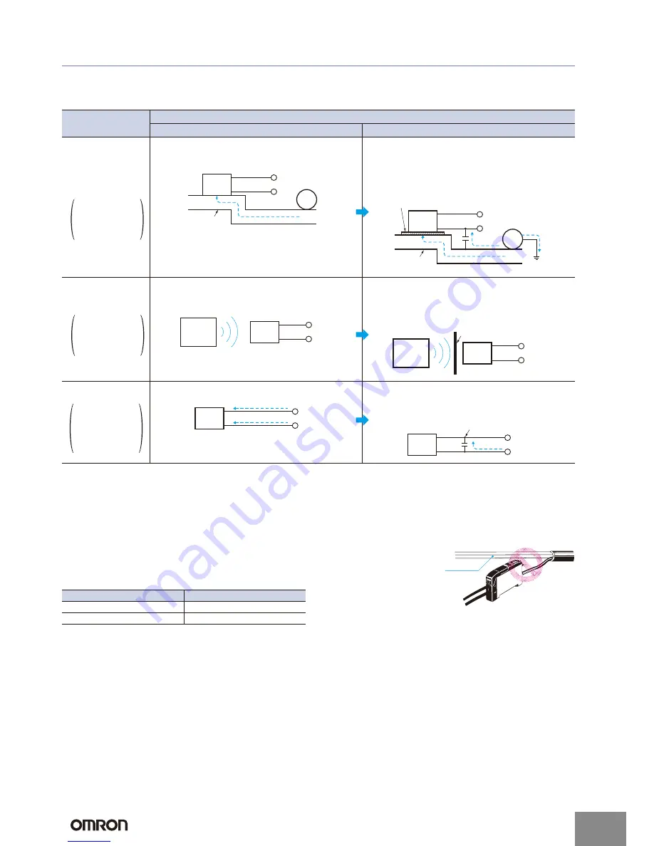
Type of noise
Noise intrusion path and countermeasure
Before countermeasure
After countermeasure
Common mode noise
(inverter noise)
Common noise
applied between the
mounting board and
the +V and 0-V
lines, respectively.
Noise enters from the noise source through the frame
(metal).
(1) Ground the inverter motor (to 100
Ω
or less)
(2) Ground the noise source and the power supply (0-V
side) through a capacitor (film capacitor, 0.22 μF, 630
V).
(3) Insert an insulator (plastic, rubber, etc.) between the
Sensor and the mounting plate (metal).
Radiant noise
Ingress of high-fre-
quency electromag-
netic waves directly
into Sensor, from
power line, etc.
Noise propagates through the air from the noise source
and directly enters the Sensor.
•
Insert a shield (copper) plate between the Sensor and
the noise source e.g., a switching power supply).
•
Separate the noise source and the Sensor to a distance
where noise does not affect operation.
Power line noise
Ingress of electromag-
netic induction from
high-voltage wires
and switching noise
from the switching
power supply
Noise enters from the power line.
•
Insert a capacitor (e.g., a film capacitor), noise filter (e.g.,
ferrite core or insulated transformer), or varistor in the
power line.
IM
Sensor
Noise
+V
0V
Inverter
motor
Mounting block
(metal)
IM
Sensor
Insert an insulator.
Inverter motor
+V
0V
Noise
Noise
Mounting block
(metal)
(3)
(2)
(1)
Noise
Sensor
Noise
source
+V
0V
Sensor
Shield plate (copper)
Noise
source
+V
0V
Sensor
Noise
Noise
+V
0V
Sensor
Insert a capacitor, etc.
Noise
+V
0V
Cable diameter
Tensile strength
Less than 4 mm
30 N max.
4 mm or greater
50 N max.
Power line
http://www.ia.omron.com/
C-3
(c)Copyright OMRON Corporation 2008 All Rights Reserved.
electronic components distributor


