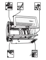
STEEL CABINET
Steel Cabinet
Safety Instructions
Assembly Steps
The steel cabinets of the SRT series serve to accommodate units of 483 mm (19") width. The cabinets
are equipped with a lockable door with acryl glass panel and removable side panels. A fan unit is
integrated in the roof. Amultiple socket outlet is included.
Maintenance and service operations are only to be carried out by authorized dealers. Damage caused
by manual modifications on this device is not subject to warranty.
If the steel cabinet and the fan unit is used for other purposes than originally intended, if it is not correctly
mounted, overloaded or not correctly connected, damage may result and the guarantee becomes void.
Avoid excessive humidity and heat. The recommended temperature range lies between -10° C and +40° C.
In order to prevent that the cabinet becomes top-heavy, heavy devices have to be mounted in the lower
part of the cabinet. The front plate of devices alone is not sufficient as a secure fastening. The devices
have to be additionally supported by side rails or a bottom carrier plate in order to reduce the pressure on
the front plate of the device and to minimize movements during transportation.
Additional space should remain above and below the devices in order to ensure sufficient ventilation and
to avoid overheating.
Caution, hazardous mains voltage! The fan unit is allowed to be operated with an alternating current
of 230 V AC, 50 Hz and was designed for indoor use only. This device falls under protection-class I.
The power plug must only be plugged into a protection class I outlet. The voltage and frequency must
exactly be the same as stated above. Wrong voltages or power outlets can lead to the destruction of
the device and to mortal electrical shock.
?
?
?
?
?
?
1. Mount the casters with screws M12 and the adjustment feet at the bottom of the base plate
(fig. [1]).
2. Fix the four side posts with screws M8 to the base plate .
3.Attach the connecting panels
with screws M6 to the side posts (fig. [3]).
4. Screw the rack rails with screws M6 to the connecting panels
(fig. [4]).
5.Attach the roof with screws M6 to the side posts .
6. Install the carrier plate, cable holder and the multiple socket outlet.
7. Put each side door in the cutouts of the base plate (fig. [7]).
8. Put the front door
in the cutouts of the base plate
and the roof
(fig. [8]). Remove the protective
foil on the front and rear sides of the acryl glas pane.
9. Connect the fan unit's power plug to a power outlet. With the power switch the fan unit can be switched
on and off.
Technical Specifications
1
Assembly Instructions
1
2
1
3
2
2
7
5
6
1
1
4
00052555.DOC, Version 1.0
100 kg
Maximum Load
30103288
100 kg
6 U
30103290
150 kg
Useable Height
30103294
10 U
16 U
Item
600 x 600 x 360 mm
Dimensions
600 x 600 x 520 mm
600 x 600 x 820 mm
18 kg
Weight
19 kg
44 kg
100 kg
30103292
12 U
600 x 600 x 805 mm
36 kg
150 kg
30103300
150 kg
20 U
30103304
200 kg
30103330
28 U
40 U
600 x 600 x 1000 mm
600 x 600 x 1360 mm
600 x 600 x 2060 mm
60 kg
61 kg
74 kg
200 kg
30103320
35 U
600 x 600 x 1820 mm
55 kg
www.omnitronic.com
EN
5
Please note: Every information is subject to change without prior notice. 10.03.2010 ©
3


