background image

M1260F Revised 12.05.06 Ver. 2 

Data subject to change without notice  


© 

Copyright OMNIFLEX 

IGM1260FR02                                                             Part Number 8.0101.036  

 
Software Requirements 

Omniset is the PC utility that is used to configure the unit. 

 
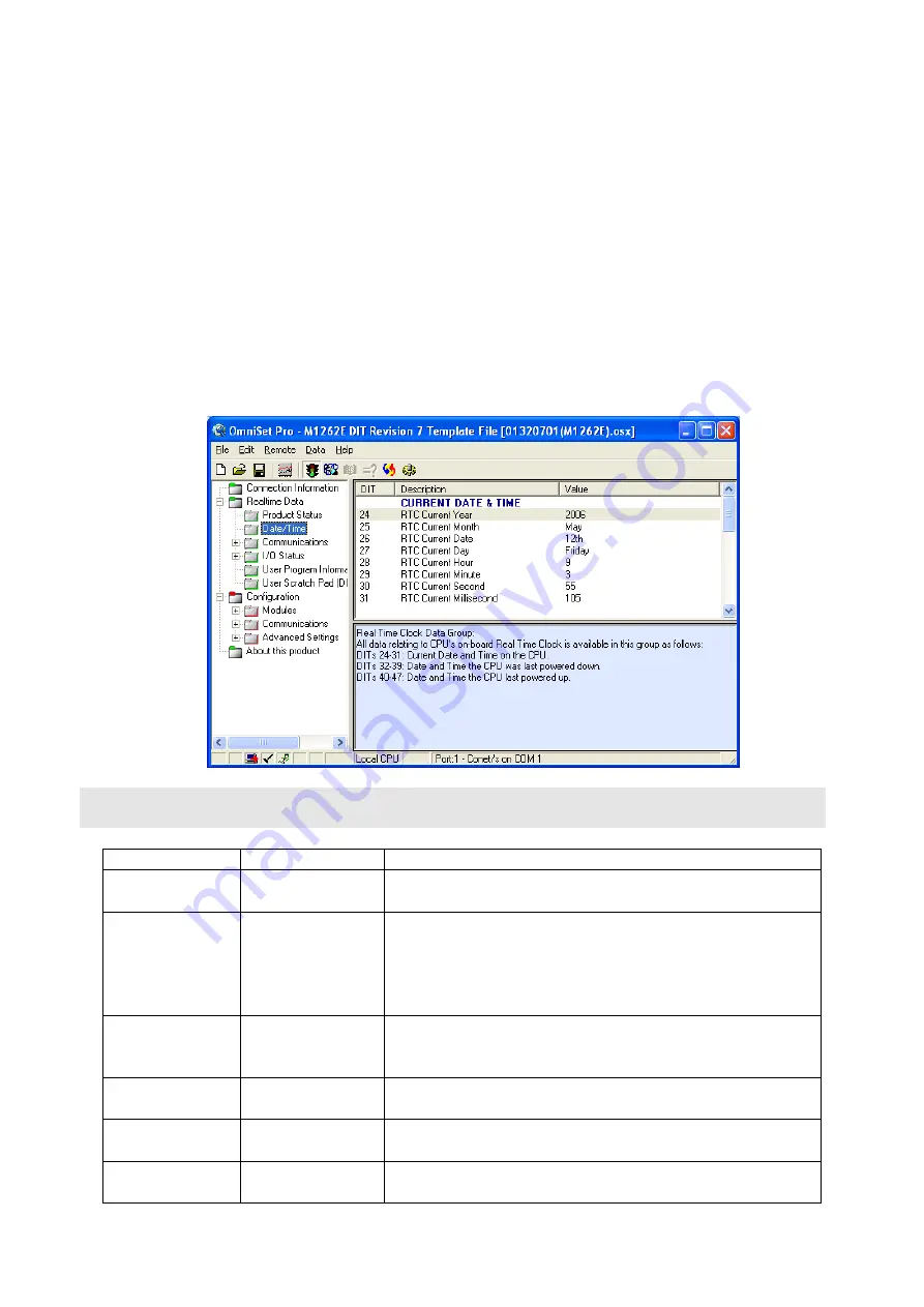
Cofiguring the Realtime Clock(RTC) 

1.  Assemble the Maxiflex base as shown in Figure 1 with the M1260 fitted into the CPU slot 

and a suitable Maxiflex PSU in the PSU slot 

2.  Connect power to your system. 
3.  Connect the M1831 programming cable between the COM port of your PC/laptop and the 

programming port of the Maxiflex CPU. 

4.  Open Omniset and click on File->Connect->Maxiflex CPU TAB. 
Select the GROUP Configuration->Ports->Realtime Data->Date/Time which is found in the left 
hand pane. Change the RTC settings by pointing the mouse to the ITEM you wish to change 
and clicking on the right mouse button and selecting the New Value option that pops up. Enter 
you new setting when prompted. Refer to screen grab below. 


Table 1: P3 CPU Front Panel Diagnostics 


LED Legend 

LED Colour 

Description 

CPU OK 

Green 

ON  - CPU is healthy 
OFF or Flashing 

– No power applied or CPU Faulty  

I/O OK 

Green 

ON - I/O Module status healthy and I/O Manifest is 
configured. 
FLASHING 

– I/O Manifest is configured but 

disagrees with installed hardware. 
OFF 

– I/O Manifest is not configured. 

RUN 

Green 

ON 

– user application software is running 

OFF 

– No user application software is running 

Flashing 

– Terminal interaction with CPU 

BATT 

RED 

ON 

– Internal battery is LOW or not connected. 

OFF 

– Internal battery is good. 

SERIAL Rx 

YELLOW 

ON 

– data is being received on serial port 

OFF 

– serial port receiver is idle 

SERIAL Tx 

RED 


ON 

– serial data is being transmitted on serial port 

OFF 

– serial port transmitter is idle 

Содержание Maxiflex P3

Страница 1: ...x master base next to the PSU module See figure 1 It has one port which is a configurable serial port This port has a DIP switch for address and parameter settings RAM is battery backed so that application program variables are not lost on power down the battery will be connected if you have an Omniflex application loaded already If you are starting with a fresh CPU from stock the battery will nee...

Страница 2: ...ouse to the ITEM you wish to change and clicking on the right mouse button and selecting the New Value option that pops up Enter you new setting when prompted Refer to screen grab below Table 1 P3 CPU Front Panel Diagnostics LED Legend LED Colour Description CPU OK Green ON CPU is healthy OFF or Flashing No power applied or CPU Faulty I O OK Green ON I O Module status healthy and I O Manifest is c...

Страница 3: ...l Transmission Mode RTU Baud rate 19200 Data bits 8 Parity none Stop bits 1 Address see dipswitch Switches 1 5 Conet ID Switches 6 8 Protocol Switch 7 ON Conet s default The default operation is to use the serial port for standard communications allowing the user to get the CPU up and running quickly and easily both on the test bench and in the field In this case the Serial Port Dipswitch beneath ...

Страница 4: ...p Bit 6 The default DTR CTS Handshaking is Off 7 The default DTR CTS Timeout ms is 0 Changing Serial Port Settings 1 Assemble the Maxiflex base as shown in Figure 1 with the M1260 fitted into the CPU slot and a suitable Maxiflex PSU in the PSU slot 2 Connect power to your system 3 Connect the M1831 programming cable between the COM port of your PC laptop and the programming port of the Maxiflex CP...

Отзывы: