© Copyright Omniflex Data subject to change without notice
M1102A Rev. 11.04.03
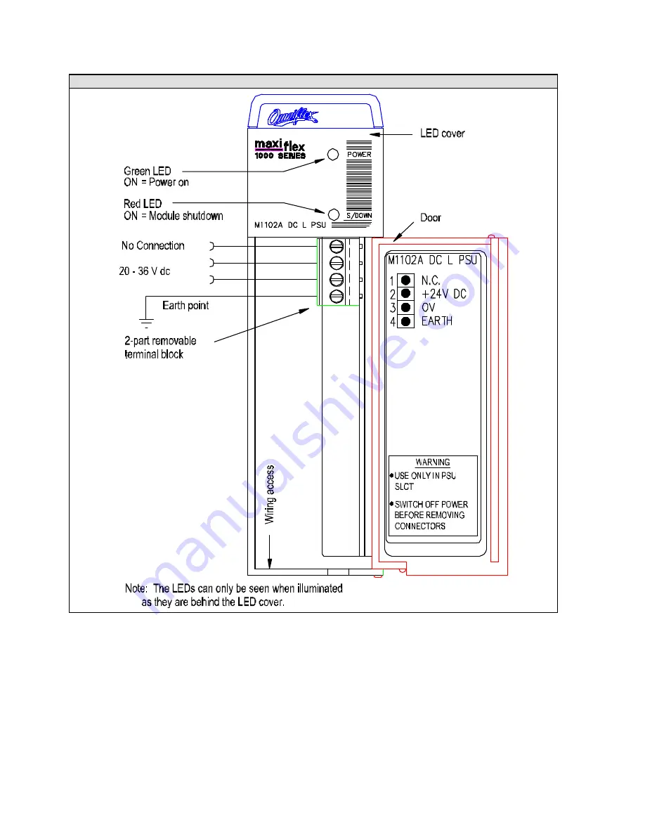
Figure 1 : Layout of M1102A Module
-
+
Страница 1: ...populated Maxiflex base under worse case conditions All connections to the module are made via the screw terminals located behind the door on the front of the module These terminals are removable for...
Страница 2: ...Copyright Omniflex Data subject to change without notice M1102A Rev 11 04 03 Figure 1 Layout of M1102A Module...
Страница 3: ...r 2 Earth Refer to Figure 1 for the external connections required Field Test Procedure The only test that is possible is observation of the two LEDs Refer to the Fault Symptom Chart for diagnosis usin...
Страница 4: ...ER 5V and 12V ok SHUTDOWN 5V output 5 9 V U 6 7 V 12V output 15 0V U 18V Isolation Input output 2 5 kVrms for 60 s Input earth 0 5 kVrms for 60 s Output earth 0 5 kVrms for 60 s Electromagnetic Compat...