


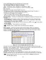

23
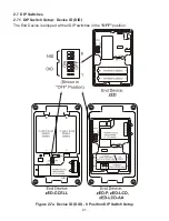
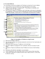
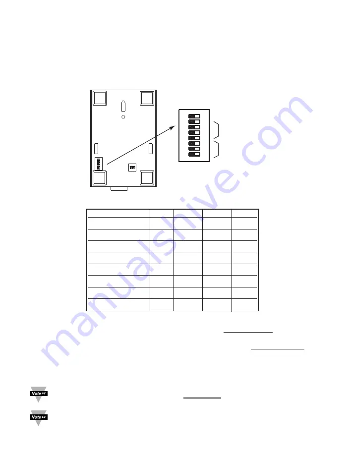
2.7.2 DIP Switch Setup: Network ID (NID)
Each sensor network has a unique
Network ID
(or NID).
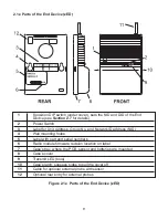
For the End Device (see
Figure 2.7
) and the Coordinator (see
Figure 2.8
) setup the
Network ID with DIP switches
#6 - 8
If there is no other IEEE 802.15.4 system, the default NID can be used where all three
dip switches are
OFF
.
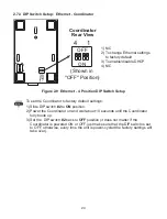
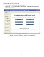
Figure 2.8 Network ID (NID) - 8 Position DIP Switch Setup
Definitions:
DID (Device ID):
The first 5 DIP switches used to assign a device number to an End
Device.
NID (Network ID):
The last 3 DIP switches used to assign a unique network number to a
network of a Coordinator and End Device(s).
PID (Personal Network ID):
The sum of the Network ID (NID) and 13106 (0x3332). The
PID as defined by IEEE for 802.15.4 standard is an identifying factor for separating
802.15.4 wireless networks to avoid overlapping and allow interoperability.
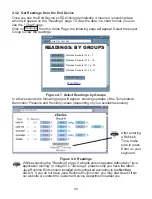
Once the End Devices and the Coordinator start communicating, make sure to push
DIP switch
#1,
located on the back of the Coordinator to the
ON
position. This will
lock the Coordinator on the same channel it initially established the connection.
It’s a good practice to record NID and DID numbers on designated labels placed
on the Coordinator and End Devices, see
Figure 2.1
and
2.5
.
OFF ON
1
8
1 SERIAL
2 DEF
AUL
T
3 DHCP
4 TERMINAL
OFF
ON
6
7
8
1
(Shown in
"OFF" Position)
2 - 5
not used
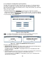
NID
PID
NID
#6
#7
#8
13106 (0x3332)
0
OFF
OFF
OFF
13107 (0x3333)
1
ON
OFF
OFF
13108 (0x3334)
2
OFF
ON
OFF
13109 (0x3335)
3
ON
ON
OFF
13110 (0x3336)
4
OFF
OFF
ON
13111 (0x3337)
5
ON
OFF
ON
13112 (0x3338)
6
OFF
ON
ON
13113 (0x3339)
7
ON
ON
ON
Coordinator
Rear View


