manualshive.com logo in svg
background image

HFS Heat Flux Sensor Instruction Manual 


2. 

Next,  calculate  heat  flux  using  the  adjusted  sensitivity  and  voltage 
measurement across the heat flux wire leads.  


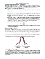
It should be noted that both positive and negative voltages can be measured by the HFS 

sensor. A negative voltage value compared to a positive voltage just means that the heat 
flux is moving in the opposite direction. 


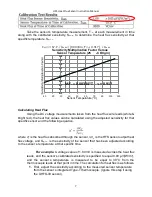
Heat Flux Sensor Sensitivity Determination


The sensor sensitivity is the output voltage induced by the sensor divided by the 

heat flux conducted through the sensor.  


Using  a  custom-made  calibration  apparatus,  Heat  flux  can  be  calculated  using  the 

measured temperature differential and a Standard Reference material

’s known thermal 

resistance. 


T

he sensor’s sensitivity can be determined by dividing the output voltage from the sensor 

by the heat flux.  


The sensitivity can then be adjusted according to the temperature accordingly.  


Where T

°C


is the sensor’s temperature in degrees Celsius & S

Calib

 is the calibrated sensor 

sensitivity provided in the table above.  


Содержание HFS-5

Страница 1: ...sensor temperature measurements The sensitivity of each sensor is provided with each unit recorded on their respective calibration certificate Sensor calibration procedures adhere to ASTM standard C11...

Страница 2: ...Heat Flux Sensor Sensitivity S V BTU ft2 hr V W m2 Temperature T F C Temperature Difference T F C Heat Flux Sensor Sensitivity at a Temperature S T C V BTU ft2 hr V W m2 Sensitivity Multiplication Fac...

Страница 3: ...tion to the temperature dependence function 6 Calculate heat flux using the adjusted sensitivity 7 Remove the sensor from the measurement surface if necessary while being very careful not to damage it...

Страница 4: ...ux Sensor Connect an ohmmeter to the bright red wire and the white wire leads to check the heat flux sensor s electrical resistance It should 1000 for HFS 5 sensors or 5 k for HFS 6 UHFS 09 sensors If...

Страница 5: ...ial number should be located on a tag on the wire leads Sensor Mounting Installation The manner in which the heat flux sensor is mounted depends on the application that it is being used for The best r...

Страница 6: ...r is removed from them IMPORTANT When removing the sensor very carefully remove the side with the leads with one hand and peel the opposite side with the other hand to avoid bending as much as possibl...

Страница 7: ...S T C is the sensitivity of the sensor that has been adjusted according to the sensor s temperature at that specific time For example A voltage value of 1 80 mV is measured across the heat flux leads...

Страница 8: ...on The sensor sensitivity is the output voltage induced by the sensor divided by the heat flux conducted through the sensor Using a custom made calibration apparatus Heat flux can be calculated using...

Страница 9: ...teel containing up to 0 35 lead by weight Exemption 6 b Lead as an alloying element in aluminum containing up to 0 4 lead by weight Exemption 6 c Copper alloy containing up to 4 lead by weight and Exe...

Страница 10: ...echa europa eu chem_data authorisation_process candidate_list_table_en asp All HFS 5 HFS 6 UHFS 09 heat flux sensor products will have the following REACH Compliance REACH Status Compliant The REACH C...

Страница 11: ...belongs to the following product Objects of the Declaration Product Model Number HFS 5 HFS 6 UHFS 09 The object of the declaration described above is in conformity with the relevant Union harmonizati...

Отзывы: