


PLATINUM
TM
Series Controllers User
’s
Guide
M5451
Omega Engineering | www.omega.com
30
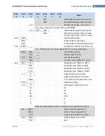
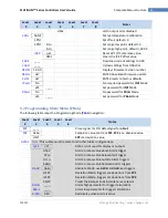
Reference Section: Initialization Mode (INIt)
Navigate to the desired scaling parameter. Options include the following:
Rd.1
–
Reading low value corresponding to
IN.1
signal
IN.1
–
Input signal corresponding to
RD.1
Rd.2
–
Reading high value corresponding to
IN.2
signal
IN.2
–
Input signal corresponding to
RD.2
In Manual Mode,
IN.1
and
IN.2
are entered manually for scaling;, in Live Mode,
IN.1
and
IN.2
activate a read of the input signal for scaling.
Select the scaling parameter to change.
For manual inputs, set the selected scaling parameter to the desired value.
Confirm the value for the selected scaling parameter in Manual Mode (
MANL
), or read and
accept the input signal for either
IN.1
or
IN.2
in Live Mode (
LIVE
).
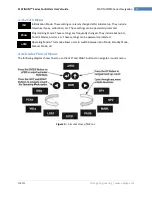
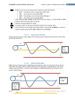
6.1.4.1
Single Ended Inputs
Single Ended inputs measure the voltage on the Analog Input terminal (AI+) with respect to the analog
ground (ARTN) terminal.
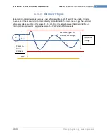
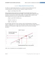
6.1.4.1
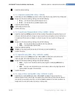
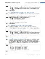
Differential Inputs
Differential inputs measure the voltage difference between the AIN+ and AIN- terminals. An internal
2.048 reference voltage (Vref) is used and determines the maximum voltage difference. The analog
voltages must be /- 2.0 volts of the analog ground (ARTN) voltage level, referred to as the
Common Mode Voltage.
ARTN
V
AIN +
Max
Input
Voltage
V
AIN +
Reference
Voltage
Common
Mode
Voltage
AIN -
ARTN


