


Page
25
from
38
13.
Set TUNE knob to maximum output power (RF POWER LED lights up max. right).
After this procedure the amplifier is tuned correctly and ready to give 1500W output power in
all operation modes with no time limited operation possibility.
At optimal tuning and full output power a positive max. 80mA current goes through the second
grid. On 24 and 28 MHz bands optimal tuning can be achieved when one or two LEDs are lit up
to the right from the position “V”. If less output is desired you can simply decrease the load of
the transceiver.
CAUTION
Should the amplifier demonstrate any malfunctions during tuning or should it not behave in
accordance witch the description, interrupt the tuning procedure immediately and check
the amplifier! Be sure to have not done any mistakes in choosing bands or TUNE/LOAD
values! Be sure that VSWR is not higher than 2:1 and input power is LOW!
After excluding possible human mistakes you will be able to work for long time with this
amplifier!
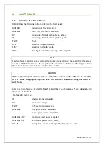
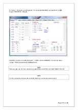
5.3.3.
Tuning Adjustment
Entering the
TUNE mode
is done by pressing the TUNE button. The OM4000A then switches the
transceiver to RTTY and sets the frequency to corresponding segment. By changing the values
of TUNE and LOAD capacitors we tune the PA as per manual tuning instructions (see 5.3.2.).
The optimally tuned amplifier will deliver full output without approaching the maximum Screen
Current of 80mA!
After tuning the amplifier save the settings by pressing SET and PA will automatically tune
frequency of your transceiver to next band segment.
Follow the same procedure for all
bands and segments if needed.
Dividing of bands into segments
Band (MHz)
1,8
3,5
7
10
14
18
21
24
28
Width of the segments (kHz)
15
30
30
30
30
50
60
60
70
By pressing MAN or AUTO buttons PA and
TCVR will return to standard operating
mode.
Содержание X8NOM4000A
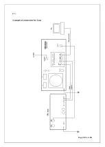
Страница 28: ...Page 28 from 38 7 1 ...
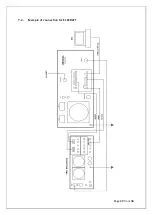
Страница 29: ...Page 29 from 38 7 2 Example of connection for ELECRAFT ...
Страница 30: ...Page 30 from 38 7 3 Example of connection with Yeasu ...
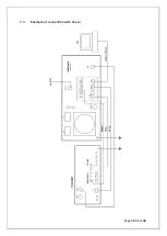
Страница 31: ...Page 31 from 38 7 4 Example of connection with antenna switch and BPF ...
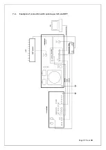
Страница 32: ...Page 32 from 38 7 5 Example of connection USB micro KEYER II with IC7800 or IC7700 ...
Страница 33: ...Page 33 from 38 7 6 Example of connection USB micro KEYER II with another Icom ...
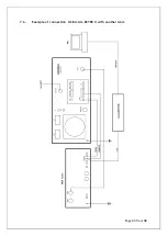
Страница 34: ...Page 34 from 38 7 7 Example for connection USB micro KEYER II with Yeasu or ELECRAFT ...
Страница 35: ...Page 35 from 38 7 8 Example of connection PA with MicroHAM MKII MK2R etc with CI V output ...