background image

34

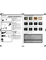
Exposure 

time lag

Trigger output

Exposure

Readout & 

transfer to PC

DP73

Trigger Output


·

The trigger output can be used to control a commercially available shutter.


·

The positive and negative logics of the trigger output can be switched with the cellSens / OLYMPUS 
Stream.


·

The trigger output is interlocked with the shutter release/close operations of the cellSens / OLYMPUS 
Stream.


·

The external trigger signal is output by starting still image acquisition when the shutter is closed.


·

The time lag from the trigger output to the start of exposure can be set between 0 and 2 sec. on the 
cellSens / OLYMPUS Stream.


·

The trigger output is a TTL compatible signal.

V

OH

: 2.4 V (min.). V

OL

: 0.4 V (max.).

Trigger Output Timing Chart in Still Image Recording (Positive logic)

Содержание DP73

Страница 1: ...familiarize yourself fully with the use of this camera we recommend that you study this manual thoroughly before operating the camera For image operations including recording editing and saving please...

Страница 2: ...the limits for a Class A digital device pursuant to Part 15 of the FCC Rules These limits are designed to provide reasonable protection against harmful interference when the equipment is operated in a...

Страница 3: ...DP73...

Страница 4: ...autions 13 4 Maintenance and Storage 14 1 SYSTEM CHART 15 2 NOMENCLATURE 16 2 1 DP73 DP73 For Desktop Computer 16 2 2 OPTIONAL DP PXU PCIe Extension Unit For Laptop Computer 18 3 HARDWARE INSTALLATION...

Страница 5: ...DP73 4 SOFTWARE INSTALLATION 29 5 IMAGE ACQUISITION PROCEDURE 31 6 EXTERNAL TRIGGERING 33 7 SPECIFICATIONS 35 9 TROUBLESHOOTING GUIDE 40...

Страница 6: ...amera adapter or a microscope from a manufacturer other than Olympus the optical performance may not be manifested fully IMPORTANT If the equipment is used in a manner not specified by this manual the...

Страница 7: ...ot slip out before setting the standby switch to ON Do not move the computer or apply an impact to it while it is powered ON 2 The cords and interface cables are vulnerable to bends or twists Do not a...

Страница 8: ...wall outlet are properly connected If the equipment is not grounded earthed Olympus can no longer warrant the electrical safety performance of the equipment 7 Lay out the interface cable so that it do...

Страница 9: ...crosoft Windows 7 refer to their respective manuals 3 Olympus guarantees the quality of this product in the factory shipment condition Olympus will not assume any liabilities for the operation errors...

Страница 10: ...of digital images for non clinical diagnostic purposes Restrictions in Use 1 The applicable camera adapter is the U TV0 5XC 3 U TV0 63XC 1 2 MVX TV0 63XC U TV1XC or the combina tion of U TV1X 2 and U...

Страница 11: ...displayed image Instability in exposure Hatching patterns in pixel shift recording 4800 x 3600 or 2400 x 1800 pixels 3CCD mode However provided that the brightness can be adjusted using the light inte...

Страница 12: ...U ULC 2 9 When the U CFU real time confocal unit is used it is required to set the exposure to a longer period than 1 30 sec using the manual exposure mode and control the brightness by engaging or di...

Страница 13: ...hifting 44800 x 3600 or 2400 x 1800 pixels 3CCD mode the image will be disturbed There are several causes for the vibration which are for example the operation of keyboard mouse on the same table wher...

Страница 14: ...r capability On board graphic also acceptable Extension slot PCI Express Rev 1 0a or later Half size or low profile PCIe board compatible 106 7 mm x 174 6 mm OS Windows 7 Professional Ultimate 64 bit...

Страница 15: ...er second The movie recording time is limited according to the HDD free space 4 RAM If a RAM other than a PC2700 or greater dual channel RAM is used the full size live frame rate may drop 5 Monitor Us...

Страница 16: ...le HDD power cable 4 pin use the provided SATA to HDD 4 pin power conversion adapter and HDD 4 pin to FDD power conversion cable for the power supply Recommended Computer Specifications Laptop Compute...

Страница 17: ...hese image files When saving movies in the HDD stack the space required for saving a movie is about 80 MB max per second The movie recording time is limited according to the HDD free space 4 RAM If a...

Страница 18: ...ay be subjected to direct sunlight high temperature humidity dust or vibrations For the operating environment conditions see chapter 8 SPECIFICATIONS on page 35 5 Be sure to install the PCIe Extension...

Страница 19: ...ays use these chemicals only in a well ventilated room 2 Parts other than the glass components should be cleaned by wiping with a clean cloth Do not use organic solvents to remove major stains Use a s...

Страница 20: ...C adapter DP PXU PCIe extension box PCIe x1 cable ExpressCard Laptop PC C mount camera adapter External trigger cable Camera interface cable Desktop PC Resolution 1260 x 1024 or higher Monitor cellSen...

Страница 21: ...e camera head should be an Olympus designated product or a product in compliance with the requirements of IEC60950 or CISPR22 24 If equipment other than these products is connected Olympus cannot guar...

Страница 22: ...size low profile size compatible PCIe Interface Board External trigger cable P 28 Clamping screws Low profile bracket P 19 Interface cable P 25 SATA to FDD power conversion cable P 19 Interface cable...

Страница 23: ...on Unit For Laptop Computer PCIe Extension Box PCIe cable connector P 26 AC adapter connector P 27 PCIe x1 cable P 26 ExpressCard AC Adapter PCIe cable connector P 26 Power cord connector P 27 Vertica...

Страница 24: ...excessively 1 2 CAUTION DP73 DP73WDR For Desktop Computer Set Figs 2 3 Before installing the PCIe interface board in the computer be sure to read the instruction manual for the computer in order not t...

Страница 25: ...ower connector e on the PCIe interface board c If your computer does not have an available FDD power cable or the FDD power cable is too short connect the provided HDD to FDD power conversion cable fr...

Страница 26: ...interface board c with low profile bracket to the connector d Connect the connector e to the PCIe interface board Attach the clamping screw b removed above A thermal conduction sheet f is attached on...

Страница 27: ...ox can be installed either horizontally or vertically Horizontal Installation Place the PCIe extension box on the desktop so that the surface with rubber feet faces down Vertical Installation Attach t...

Страница 28: ...ecision modules Be careful not to drop them during attaching or detaching The following procedure deals with the case using the U TV1XC C mount camera adapter Screw in the U TV1XC C mount camera adapt...

Страница 29: ...using other manufacturer s C mount camera adapter or C mount lens having a thread length c over 4 5 mm Otherwise the threaded section will hit the inside of the camera head and cause damage to it Be...

Страница 30: ...amera head Computer PCIe Extension Box side Connecting the Interface Cable Figs 9 10 Insert the connector of the interface cable all the way into the connector a of the camera head and secure the clam...

Страница 31: ...ressCard 34 slot Hold the card with the surface marked INSERT facing up and insert ExpressCard 54 slot Hold the card with the surface marked INSERT facing up and insert it along the left edge of the s...

Страница 32: ...to chapter PROPER SELECTION OF THE POWER SUPPLY CORD at the end of this instruction manual If the equipment is not grounded earthed Olympus can no longer warrant the electrical safety performance of...

Страница 33: ...n the computer or the PCIe extension box When using the trigger input connect the red cable marked I b to the BNC connector When using the trigger output connect the white cable marked O c to the BNC...

Страница 34: ...running applications before installing cellSens or OLYMPUS Stream The software cannot be installed unless the user account is registered as computer administrator If the user account is registered as...

Страница 35: ...at the selection of devices in the cellSens OLYMPUS Stream An device list is displayed at the time of first start up of the software The device list can be also displayed by clicking the tabs of Acqu...

Страница 36: ...ance Record an image Select the area 30 1 0 1 full image Set the exposure time Exposure mode Manual Auto Save the image Fine adjust the exposure time Exposure mode Manual Auto For the details refer to...

Страница 37: ...the area and correct exposure Adjust the black balance Record an image Select the area 30 1 0 1 full image Set the exposure time Exposure mode Manual SFL Auto Save the image Fine adjust the exposure t...

Страница 38: ...ernal equipment can be used to start still image acquisition using the cellSens OLYMPUS Stream The trigger input is detected at the edge and the cellSens OLYMPUS Stream starts to acquire the images ba...

Страница 39: ...trigger output is interlocked with the shutter release close operations of the cellSens OLYMPUS Stream The external trigger signal is output by starting still image acquisition when the shutter is cl...

Страница 40: ...CD Total pixels 2 1 million pixels Effective pixels 2 01 million pixels Pixel pitch 4 40 m H x 4 40 m V Scanning method progressive scanning Cooling Peltier cooling Natural air cooling CCD temperature...

Страница 41: ...l AE lock Available Exposure correc tion Correction range 2 0 EV Step 1 3 EV Metering area Full image 30 1 0 1 The metering area is freely movable Exposure time 1 44 000 to 60 sec Binning 2 x 2 Live f...

Страница 42: ...mage accumulation Modes Integral averaging Accumulation count 64 frames max White balance modes Area specified auto Manual Black balance modes Area specified auto Manual Contrast modes Low Standard Hi...

Страница 43: ...formats Dependent on the application software Preview quality modes Standard Medium High Computer interface PCI Express Rev 1 0a or later Desktop computer Compatible with half size or low profile siz...

Страница 44: ...pressCard 100 W x 34 D x 11 H mm excluding projections approx 25 grams AC adapter 61 W x 133 D x 41 H mm excluding projections approx 480 grams Cord length Approx 2 0 meter 100 240V 2A 50 60Hz PCIe x1...

Страница 45: ...head and computer properly 25 The software is installed improperly Install the software 29 Live image is not displayed The camera and computer are connected improperly Connect the camera head and com...

Страница 46: ...ording processing completes before starting recording of the next image In certain cases it may be required to press the Cancel button on the status bar and record the image again Online manual The ce...

Страница 47: ...etering area to the area where you want to obtain optimum exposure Online manual AE lock which was set when the exposure time was longer than the currently required exposure time is active Cancel AE l...

Страница 48: ...a to the area where you want to obtain optimum exposure Online manual AE lock which was set when the exposure time was shorter than the currently required exposure time is active Cancel AE lock Online...

Страница 49: ...the RGB color balance to obtain optimum colors Online manual The area selected in black balance adjustment was improper Select a black area with the rectangular black balance adjust ment area Online m...

Страница 50: ...over glass on the front of the camera is stained Clean the objective camera adapter lens condenser and or window lens of the microscope or clean the cover glass on the bottom of the camera head 14 The...

Страница 51: ...ens or OLYMPUS Stream window is not displayed correctly or the menu characters are not displayed correctly The resolution setting of the screen is incorrect Set the resolution setting at 1280 x 1024 o...

Страница 52: ...pproved power supply cord for Olympus products Olympus can no longer warrant the electrical safety of the equipment Specifications Voltage Rating Current Rating Temperature Rating Length Fittings Conf...

Страница 53: ...Table 1 In case you are unable to buy locally the power supply cord which is approved by one of the agencies mentioned in Table 1 please use replacements approved by any other equivalent and authoriz...

Страница 54: ...49 Country Agency Certification Mark Country Agency Certification Mark Finland FEI Switzerland SEV France UTE United Kingdom ASTA BSI Germany VDE U S A UL Ireland NSAI...

Страница 55: ...ead Length of color section in mm Black Red Yellow Comite Electrotechnique Belge CEBEC CEBEC HAR 10 30 10 Verband Deutscher Elektrotechniker VDE e V Pr stelle VDE HAR 30 10 10 Union Technique de I Ele...

Страница 56: ...MKO HAR 10 10 70 Asociacion Electrotecnica Y Electronica Espanola AEE UNED HAR 30 10 70 Hellenic Organization for Standardization ELOT ELOT HAR 30 30 70 Instituto Portages da Qualidade IPQ np HAR 10 1...

Страница 57: ...DP73 MEMO...

Страница 58: ...MEMO...

Страница 59: ...DP73 MEMO...

Страница 60: ...2011 12 02...

Отзывы: