Complete Teardown, Cleaning, and Reassembly of the Olympus BHSU/BHTU Reverse Nosepiece Assembly
Revision 3
Page 4 of 19
Figure 41
–
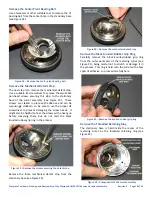
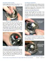
Apply grease to the five detent notches ............................................................................................................ 15
Figure 42
Place cover in position on the turret assembly .................................................................................................. 15
Figure 43
Secure protective cover using three screws ...................................................................................................... 15
Figure 44
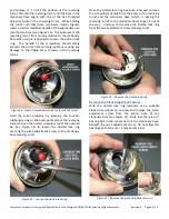
Apply black silicone RTV to revolving turret ...................................................................................................... 15
Figure 45
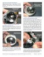
Reinstall the knurled-rubber grip ring ................................................................................................................ 16
Figure 46
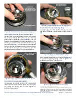
Remove any silicone RTV squeeze-out .............................................................................................................. 16
Figure 47
Place the wedge mount in position ................................................................................................................... 16
Figure 48
Reinstall the corrective-optics assembly ............................................................................................................ 16
Figure 49
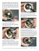
Reinstall screws to secure the wedge mount .................................................................................................... 16
Figure 50
Tighten the corrective optics assembly ............................................................................................................. 17
Figure 51
Hold reverse nosepiece assembly up to arm ..................................................................................................... 17
Figure 52
Align holes for the mounting screws .................................................................................................................. 17
Figure 53
Reinstall three screws to secure it to the arm ................................................................................................... 17
Страница 1: ...this PDF document in its entirety for personal non commercial purposes only provided that the contents are not modified in any way including the copyright notices contained herein This document may be...
Страница 2: ...chanical Detent Stop 10 Remove the Black Knurled Rubber Grip Ring 10 Remove the Threaded Retaining Ring 10 Remove the Perimeter Bearing Balls 11 Remove the Stationary Base from the Turret 11 Thoroughl...
Страница 3: ...n the slotted lock ring 9 Figure 16 Remove the slotted lock ring 9 Figure 17 Remove the pivot adjustment screw 9 Figure 18 Remove the center pivot bearing ball 10 Figure 19 Remove the screws securing...
Страница 4: ...silicone RTV to revolving turret 15 Figure 45 Reinstall the knurled rubber grip ring 16 Figure 46 Remove any silicone RTV squeeze out 16 Figure 47 Place the wedge mount in position 16 Figure 48 Reinst...
Страница 5: ...he Olympus BHSU and BHTU microscope stands Note that the original Olympus service literature did not address the teardown and repair of the various revolving nosepiece assemblies used on BH 2 stands a...
Страница 6: ...st of solvents generally considered safe for nylon includes acetone diethyl ether heptane mineral spirits naphthalene and turpentine Before Starting with the Overhaul Before beginning the removal and...
Страница 7: ...ing the wedge mount to the stationary base of the turret assembly see Figure 6 It is important to remove these four screws before attempting to remove the corrective optics assembly to prevent the bar...
Страница 8: ...pivot adjustment screw unless you have access to such a tool since the slot in the lock ring will likely be damaged if you use an improper tool making removal of the lock ring much more difficult1 A...
Страница 9: ...g the knurled rubber grip ring on the outer perimeter of the revolving turret and use the slotted screwdriver with the notched tip see Figure 13 to loosen the slotted lock ring securing the pivot adju...
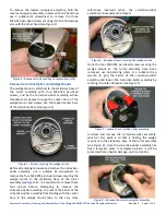
Страница 10: ...ent damaging the screw heads It might also be helpful to heat the screws with a heat gun before loosening them but do not melt the black knurled rubber grip ring in the process Figure 19 Remove the sc...
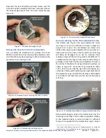
Страница 11: ...th the threaded retaining ring do not fall out and become lost in the process see Figure 24 Figure 24 Remove the threaded retaining ring Remove the Perimeter Bearing Balls Carefully remove the 3 32 be...
Страница 12: ...rease for the bearing balls Reinstall the Perimeter Bearing Balls Use tweezers to carefully set the 3 32 bearing balls there are 80 of them into the grease ring see Figure 29 placing the bearing balls...
Страница 13: ...at the center pivot bore has been greased reinstall the bearing ball into the freshly greased center pivot bore The grease will hold the center pivot bearing ball in the proper position during subsequ...
Страница 14: ...t with the other hand The motion of the turret should not feel gritty erratic or excessively stiff If it does loosen the slotted lock ring readjust the pivot adjustment screw and retighten the slotted...
Страница 15: ...o the stationary base see Figure 43 Figure 43 Secure protective cover using three screws Reinstall the Knurled Rubber Grip Ring The final assembly step for the turret assembly is to reinstall the blac...
Страница 16: ...sition While holding the wedge mount in this position place the threaded end of the corrective optics assembly through the center bore of the wedge mount and screw the corrective optics assembly into...
Страница 17: ...anical detents thereby maximizing the useful service life of the reverse nosepiece assembly Follow the procedures detailed in this document to remove the reverse nosepiece assembly from the microscope...
Страница 18: ...may be encountered if the threaded retaining ring has not been properly snugged down or if the center pivot adjustment screw has not been properly adjusted to remove the play in the center pivot mech...
Страница 19: ...on 5 40 4 Bearing balls stainless steel 1 4 G25 25 count various Amazon 4 95 5 Pliers soft jaw Non Scratch Pliers Micro Mark 85161 34 95 Pliers soft jaw Tamiya 74061 Amazon 32 64 6 Lens spanner tool p...