Teardown, Cleaning, and Reassembly of the Miscellaneous Parts of the Olympus BH-2 Microscope Frames
Revision 1
Page 35 of 45
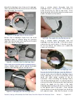
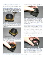
Use a suitable lens suction tool (item 9 of
to carefully install the clear adiabatic glass disk into the
metal barrel and seat it on the upper spacer tube (see
Figure 145
–
Install adiabatic disk into the metal barrel
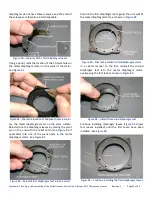
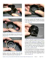
Use a suitable lens spanner tool (item 8 of
to reinstall the upper retaining ring (the larger of the
two) into the metal barrel and snug it down against the
adiabatic glass disk (see
and
Figure 146
–
Place upper retaining ring into position
Figure 147
–
Snug upper retaining ring to the glass disk
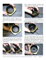
The Light Inlet Assembly is now ready to be reinstalled
into the microscope stand (see
).
Figure 148
–
Ready to reinstall the Light Inlet Assembly
Reinstall Light Inlet Assembly (BHT/BHTU)
Observe the outer surface of the metal barrel of the
Light Inlet Assembly to find the two bite marks in the
circular depressions machined into the metal barrel (see
). Since these bite marks were made by the
setscrews that originally secured the Light Inlet
Assembly in the correct location in the base casting,
they can be used as witness marks to reinstall the Light
Inlet Assembly back into its original location.
Figure 149
–
Bite marks to act as alignment witness marks
Carefully insert the light inlet assembly into the bore of
the base casting, as shown in
Figure 150
–
Insert Light Inlet Assembly into the bore


