Date
9/7/2018
File
BSR-2114/MAR
Document Number
921211401_09_002
Page
21 από 74
21
R
e
la
y3
R
el
ay
2
R
el
ay
1
FA
U
LT
PA
N
IC
R
E
S
E
T
D
O
O
R
A
LA
R
M
Connection with
main P.C.B.
REL1
REL2
REL3
REL4
REL5
REL6
6
R
el
ey
f
o
r
g
e
n
er
al
u
se
Connection
with printer
USB output
for PC connection
Loop
Output
Panel
Interface
R
el
ay
6
P
an
e
l I
nt
er
fa
ce
Lo
op
E
xt
en
si
on
R
el
a
y6
R
el
ay
6
R
el
ay
5
R
el
ay
5
R
el
ay
5
R
el
ay
4
R
el
ay
4
R
el
ay
4
Other
Outputs
External
device power supply
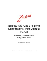
Figure 3-3
Input/Output board
Extension
Output
Loop
Output
Other
Outputs
P
an
el
In
te
rf
ac
e
E
xt
en
si
on
Lo
op
Relay 3
Relay 2
Relay 1
Relay 4
Fire Alarm
Routing
FAULT
PANIC
RESET
DOOR
ALARM
Relay 5
Relay 6
Figure 3-4 Input/Output board terminal blocks
Figure 3-4
shows the connection terminal block found on the right side of the input/output board.
The paragraph below will describe in detail the function of each signal.