Page
4 from
5
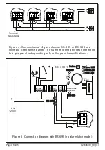
Figure 4. Connection of 4 gas detector BS-685 or
BS-686 to a
Olympia Electronics panel. The number of the devices connecting
to a gas panel is depending only to the panel specifications.
Ζ
1
2
4
V
_
M
Terminal
Resistance
5
Κ
6
BS-685-6
BS-685-6
BS-685-6
BS-685-6
Figure 5. Connection diagram with BS-690 (no alarm latch mode)
NC
C
NO
N
+
L
OUT
GND
Z+
Z -
+VS
GND
S
EXTERNAL
BUZZER
Sensor
JMP1
JMP2
JMP3
L N
~230 V
A B
Power LED
RED LED
RED LED
Alarm LED
Fault LED
Button
1
1
1
SENSOR
BS-655
5Κ6
BS-690-1
B
S
-6
8
5
-6
921686000_09_01
7


