Page
2
from
5
the line(see figure 2).
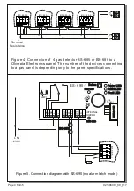
Connection with others fire panel.
Terminals NO, C are used to connect to the zone
of the gas panel, as shown in figure 2. A terminal
resistor should be installed on the end of the line
(see figure 3).
Programming Alarm latch mode
When the device is in alarm mode, it keeps its
condition even if the contents drop below 5-15%
of the L.E.L. This is an alarm latch mode. This
mode is helpful to the technician, to locate the
device which is in alarm condition.
When you connect the device to a conventional
gas panel, the device must have alarm latch
mode. If we want to de-activate the alarm latch
mode, the LD1 jumper must be linked. The link
or the removal should be done when the unit is
not operating. The device is shipped with
activated the alarm latch.
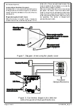
Figure 1. Diagram of removing the plastic cover
Ζ
1
2
4
V
_
M
5
Ê
6
Terminal Resistor
LED Alarm
Jumper for programming
alarm latch mode
Fire panel
Olympia Electronics
Relay resistance
selection jumper
Figure 2. Connection diagram of a detector
with a fire panel of Olympia Electronics
921686000_09_01
7
These screws must be
unscrewed in order to remove
the plastic cover
The sensor must
faced downwards
LED Alarm
Gland for cable
connection


