


Page 7 from 22
921316000_09_016
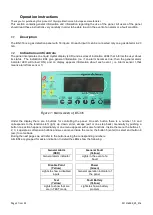
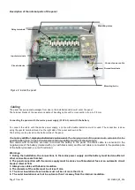
Description of the internal parts of the panel
Cabling
The panel has pre-opened passages from where the installation cables will enter the panel.
The terminal blocks of the panel are capable of handling cable with a cross-section of up-to 2.5mm.
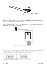
Connecting the panels with the mains power supply (230V AC) and with the battery
To connect the cable with the mains power supply, a cable with double insulation must be used. The connection is done
using the special terminals found on the right side of the panel as shown in the.
The battery can be placed on the bottom side of the panel.
The battery
Α-986
of
olympia electronics can be used
. The charging circuit of the panel is also calculated for the
specific battery type. In case of replacement, the new battery must be of the same type.
Two cables with connectors are used to connect the battery to the panel. The black cable is connected to the
negative pole of the battery (marked with (-) or with black color) and the red cable is connected to the positive pole
of the battery (marked (+) or with red color).
Warnings.
1. During the installation, the connections to the mains power supply and the battery must be done after all
other connections are finished.
2. The panel connection with the mains supply must be done via a 16A external fuse or an automatic circuit
breaker rated at 16A.
3. Always use cables with double insulation.
4. The diameter of the cable must be at least 1mm.
5. The inner insulation of each cable must not be cut more than 1cm
6. The outer insulation must not be cut more than 1cm away from the internal insulation.
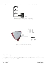
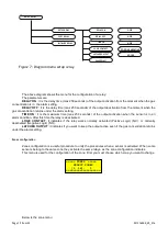
Figure 2: Inside the panel
Mounting holes
Mounting holes
Place batteries
Connect power cable
Ground terminals
Relay terminals
Inputs terminals


