


Page 4 from 22
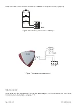
921316000_09_016
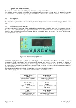
1.3
Access level 1
This level contains 2 functions that can be implemented by pressing a single key.
-
In the event of an Alarm or Fault condition, if the key number (1) is pressed then the internal buzzer is
silenced. For as long as the event is in effect the internal buzzer sounds once in every 30 seconds. Should
the panel see a new event in this state then the buzzer will start to sound continuously.
-
When the panel is in standby mode (no alarm or fault events have occurred) then if the key number (2)
(lamp test) is pressed the system conducts a sequential LED and Display test.
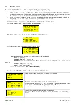
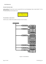
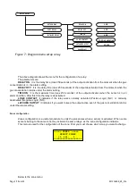
When the system is in quiescence state, the lcd screen shows info about the system.
The below screen shows some information about the system
The below screen shows the panel name and the technician information.
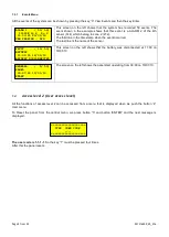
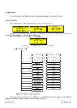
The next screen shows the condition of each sensor (input)
The sensors 4-20mA incorporates the current have the next situations:
FAULT -
(<1 mA)
UNDERFLOW
(from 1 to 3.5 mA)
NORMAL
(from 3.5 to 21 mA) inside these limits we can do the setup of alarm 1, alarm 2 and
alarm 3)
OVERFLOW
(from 21 to 24mA)
FAULT+
(24mA and Higher).
There is the disable situation (
ΝΟ CONFIGURATION
)
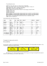
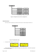
In case alarm or fault the LCD display shows the corresponding message.
This screen shows a summary of the events in the system.
The alarm screen show which inputs are in alarm condition.
For example the second line 4: 14% LIE ALARM 2 means that the 4th input
sensor has detected 14% LIE of a gas and it is at ALARM 2 state.
The screen on the left shows the faults of the system.
For example the second line 1: FAULT + means that the 1st input sensor has a
FAULT +.
EVENTS IN SYSTEM
ALARMS 10
FAULTS 5
ALARM
10
4: 14%LIE ALARM 2
9: 60ppm ALARM 3
16: 20ppm ALARM 1
FAULT
5
1: FAULT +
3: FAULT -
BATTERY
OLYMPIA ELECTRONICS
BS-316 V.055
12:00:00 20/01/10
SYSTEM READY
PANEL NAME
MAIN BUILDING
TECHNICIAN INFO
OLYMPIA ELECTRONICS
1: 0%LIE NORMAL
2: NO CONFIGURATION
3: NO CONFIGURATION
4: 5ppm NORMAL


