I
MPACT
E
CHO
(IE)
www.olsoninstruments.com
www.olsonengineering.com
Impact Echo (IE)
– IE
investigations are performed to assess the condition of slabs, beams, columns,
walls, pavements, runways, tunnels, and dams. Voids, honeycomb, cracks, delaminations and other
damage in concrete, wood, stone, and masonry materials can be found utilizing the IE method. IE
investigations are also performed to predict the strength of early age concrete if the member thickness is
known and to measure the thickness of structural members. An advantage of the IE method over the
Ultrasonic Pulse Velocity (UPV) method is that only one side of the structure needs to be accessible for
testing. In addition, the IE method will provide information on the depth of a flaw or defect, in addition
to mapping its lateral location and extent. For large area investigations such as slabs, bridge decks,
beams, pipes, etc. where shallow voids or delaminations are of primary concern, Olson Instruments
manufacturers an IE Scanner, which can record data at 1 to 2 inch increments for an entire scan path. IE
Scanning is used in locating post-tensioning (PT) cables used in reinforcing various structures and
determining duct grout condition. The scanning technology allows tracing of the PT cables through slabs
and beams. The scanning device application of the IE method was developed by Olson Instruments and is
a patented technology. For simple investigations on slabs, pipes, or walls where the overall thickness is
the primary concern, a hand-held NDE360 with an Impact Echo option will quickly and easily provides
the thickness of an unknown concrete member.
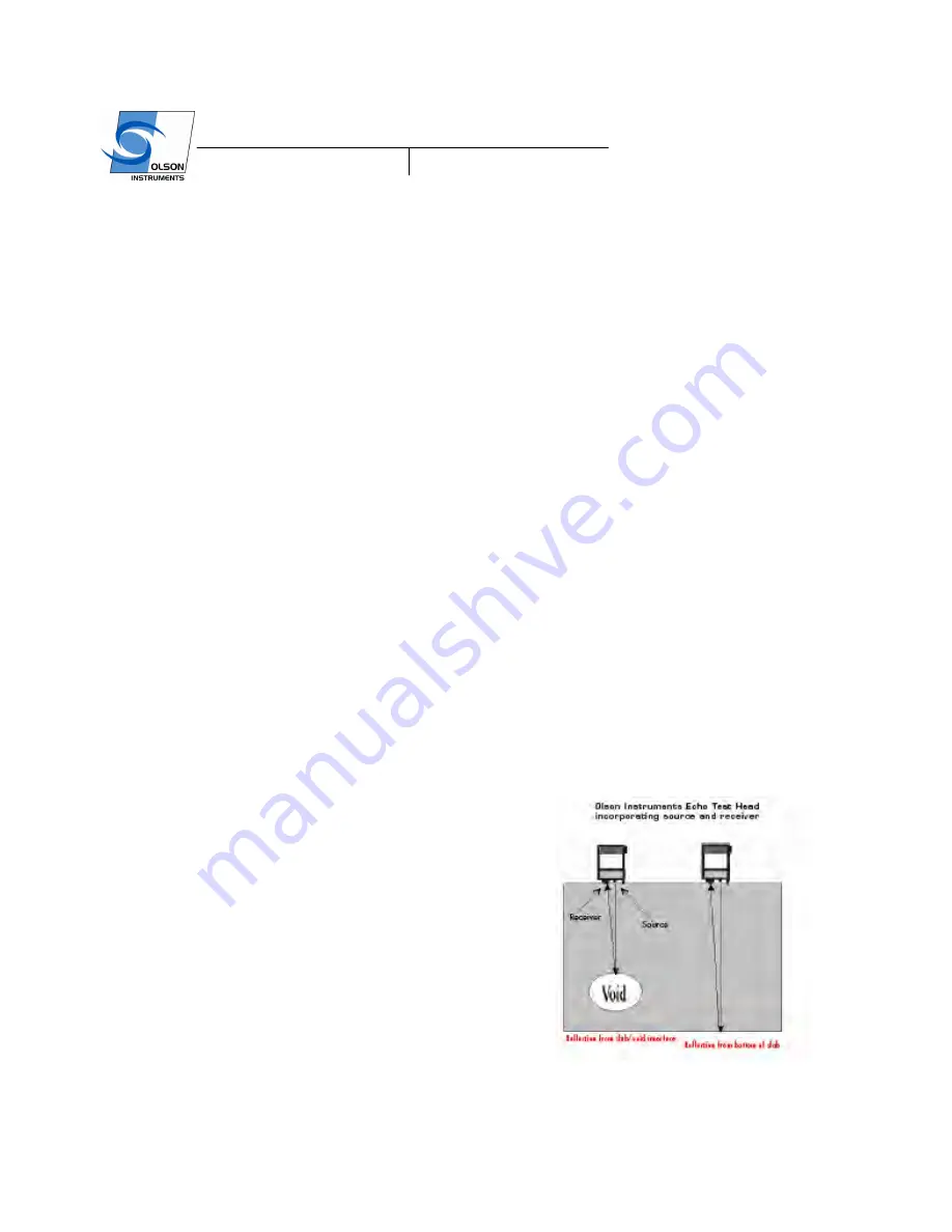
The IE tests involved impacting the concrete/masonry member with an impactor solenoid and identifying
the reflected wave energy with a displacement transducer as shown in the figure below. Note that the
solenoid impactor and a displacement transducer are built in the IE head. The test head was pressed
against the top of the tested member and held while tests were performed at each test point. The resonant
echoes of the displacement responses are usually not apparent in the time domain, but are more easily
identified in the frequency domain. Consequently, amplitude spectra of the displacement responses are
calculated by performing a Fast Fourier transform (FFT) analysis to determine the resonant echo peak(s).
The relationship among the resonant echo depth frequency peak (f), the compression wave velocity (V
P
)
and the echo depth (D) is expressed in the following equation:
D =
β
V
p
/(2*f)
(1)
where
β
is a geometric shape factor equal to from 0.8 for a
pier/column shape to 0.96 for a slab/wall shape. A slab/wall
shape has a single thickness resonance while beam and
column shapes have multiple resonances due to their cross-
sectional shape.
1.2
Test Methodology


