background image

DISASSEMBLING THE FIXED CUTTER BLADE  

The operation described in this section can be displayed by clicking on the link: 

FIXED CUTTER BLADE DISASSEMBLY.MP4


To remove the fixed blade of the cutter, proceed as follows: 

1.

Disassemble the printer assy. See 

DISASSEMBLING THE PRINTER GROUP”

.

2.

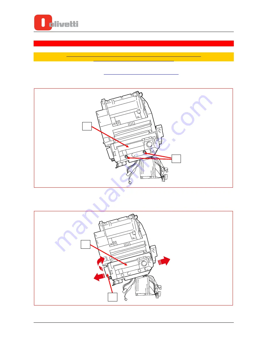
Undo the two screws (1) indicated in the figure which fasten on the protective cover of the printhead and the
cutter fixed blade (2).

4-10


Service Manual

Y117850-4

Figure 4-16 

3.

Warping slightly the protective cover (2) first on the left side and then on the right, lift it in the direction indicated
by the arrow using the flap (3).

Figure 4-17 

Содержание NETTUNA 7000 Open

Страница 1: ...Cash Register NETTUNA 7000 Open SERVICE MANUAL Code Y117850 4...

Страница 2: ...PUBLICATION ISSUED BY Olivetti S p A Telecom Italia Group Via Jervis 77 10015 Ivrea TO Copyright 2015 Olivetti All rights reserved...

Страница 3: ...ash register modules Chapter 4 Describes the procedures which must be followed to disassembly the printing unit Chapter 5 Troubleshooting and connectors pin out The following video clips are also avai...

Страница 4: ...Page intentionally left blank...

Страница 5: ...METERS 1 17 Chapter 2 INSTALLATION AND MAINTENANCE PROCEDURES 2 1 INSTALLATION PROCEDURE 2 1 Loading the receipt paper roll 2 1 Calibrating the near end of paper sensor 2 3 Installation adapter for pa...

Страница 6: ...CUTTER BLADE 4 4 DISASSEMBLING THE CUTTER MOTOR AND SENSOR 4 7 DISASSEMBLING THE PAPER SENSOR 4 9 DISASSEMBLING THE FIXED CUTTER BLADE 4 10 DISASSEMBLING THE PAPER FEED MOTOR 4 13 DISASSEMBLING THE PR...

Страница 7: ...esistive the thermal printhead has 576 dots with print width of 72 mm the customer display is an alphanumeric 20 characters x 2 lines As options are available the Fingerprint Reader and the remote dis...

Страница 8: ...Internal View 1 2 Service Manual Y117850 4 Figure 1 2 REFERENCE DESCRIPTION 9 PRINTING UNIT 10 PAPER ROLL 11 COVER OPEN SENSOR 10 11 Near end of paper lever 9 Clam release lever...

Страница 9: ...e package contains the following components Cash Register Nettuna 7000 Open Power Cable 1 External Power Unit 2 Paper Roll 3 Paper Roll Adapter 4 User Manual slim edition 1 Y117850 4 Service Manual 1...

Страница 10: ...Audio out 1 Microphone 1 Customer Display 1 RJ12 Cash Drawer port DRW DISPLAY TFT 10 1 inch Resolution 1024 x 600 Interface LVDS 18bit 3 3V LED Backlight TOUCH SCREEN 4 wire resistive CUSTOMER DISPLAY...

Страница 11: ...LTE USB router ADSL Digicom ADSL2 Combo C Ethernet Modem Router mod 8E4411 Cash drawer DTW 450 DRW 650 Barcode Reader keyboard emulation Datalogic Magellan 1100i Point of Sale Handable Scanner Honeyw...

Страница 12: ...ure 1 4 CUSTOMER DISPLAY REMOTE DISPLAY LVDS TOUCH CONTROLLER USB5 USB4 COM1 COM2 CASH DRAWER VIDEO LCD AND TOUCH SCREEN PRINTER FINGERPRINT READER POWER SUPPLY 12V USB7 USB0 USB1 LAN VGA HDMI USB2 US...

Страница 13: ...BOARD 3 VGA PORT PC BOARD 4 2 USB 2 0 PORTS USB2_3 PC BOARD 5 HDMI PORT PC BOARD 6 LINE OUT PC BOARD 7 MICROPHONE PC BOARD 8 ON OFF TOGGLE SWITCH PC BOARD 9 SERIAL INTERFACE POLARIZED FOR DISPLAY EPS...

Страница 14: ...Figure 1 6 1 8 Service Manual Y117850 4...

Страница 15: ...RD DEVICE REFERENCE J3 24V POWER SUPPLY JS1 PRINTER BOARD J4 NOT USED J17 NOT USED J5 SIGNALS J9 PRINTER BOARD J9 NOT USED J10 RS 232 COM1 PC BOARD COM6 PC BOARD J13 ON OFF MACHINE ON OFF SWITCH J14 N...

Страница 16: ...PRINTER BOARD The Printer Board connectors are described in this section Figure 1 8 1 10 Service Manual Y117850 4...

Страница 17: ...T J5 CLAM OPEN PHOTOSENSOR PRINTER UNIT J6 PAPER PRESENCE PHOTOSENSOR PRINTER UNIT J7 NEAR END OF PAPER PHOTOSENSOR PRINTER UNIT J9 PRINTER BOARD I O BOARD SIGNALS J5 I O BOARD J12 TOUCH SCREEN VIDEO...

Страница 18: ...PC BOARD The PC Board connectors are described in this section Figure 1 10 1 12 Service Manual Y117850 4...

Страница 19: ...OM3 5V PRINTER BOARD START SIGNAL J14 PRINTER BOARD USB4_5 USB FINGERPRINT READER J13 J15 PRINTER BOARD USB6_7 USB FINGERPRINT READER CONTROLLER CARD SYSTEM PANEL HEADER POWER KEY CABLE UPPER BODY POW...

Страница 20: ...the jumper for Normal operation CLRCMOS1 Figure 1 12 Backlight Power Selection BKT_PWR1 Setting PIN SIGNAL NAME 1 5V 2 NC 3 LCD_BLT_VCC 4 Vin 5 12V 6 NC Insert the jumpers onto pins 3 and 5 to select...

Страница 21: ...E 1 3 3V 2 NC 3 LCD_VCC 4 12V 5 5V 6 NC Insert jumpers onto pins 1 and 3 to select a voltage of 3 3V see Figure 1 16 When a PC Board is supplied as a spare part this setting must always be done Y11785...

Страница 22: ...r and those of the PC Board have the following matches SER 1 COM 6 and SER 2 COM 1 CASH REGISTER COM PORT REFERENCE PC BOARD JUMPERS AND COM REFERENCE PIN SIGNAL NAME 1 5V 2 Common SER 1 3 12V 1 5V 2...

Страница 23: ...otstrap the Cash Register and typing the password SVPWD with lowercase characters Navigating the BIOS is comparable to that of the most common PC The parameters on Nettuna 7000 Open may require change...

Страница 24: ...1 18 Service Manual Y117850 4 This page is intentionally left blank...

Страница 25: ...following messages on the touch screen Near end of paper Notifies that the roll of thermal paper is almost finished In this condition the printer continues to function normally until the thermal pape...

Страница 26: ...assy and extract the finished receipt roll 5 Unwind approximately 20 cm of paper from the new roll then insert the roll into its compartment inside the printer 6 Lower the printhead and cutter assy a...

Страница 27: ...orrect functioning for the most commonly used paper rolls If too much or too little paper remains when the near end of paper condition is notified you can regulate the sensors Regulation depends on th...

Страница 28: ...e the paper compartment cover 7 Turn on the cash register as described in the section TURNING ON THE CASH REGISTER Installation the paper roll adapter The paper roll adapter is illustrated in the foll...

Страница 29: ...he adapter correctly into their respective reference slots depending on the size of roll to be used The photo below shows the positions of the slots inside the paper roll compartment Figure 2 8 Positi...

Страница 30: ...egister as described in the section TURNING ON THE CASH REGISTER on page 2 6 Turning on the cash register 1 Ensure that the power unit is connected to the cash register and to a power outlet The power...

Страница 31: ...2 Press the power key Figure 2 7 Y117850 4 Service Manual 2 7...

Страница 32: ...2 8 Service Manual Y117850 4 This page is intentionally left blank...

Страница 33: ...carrying out in reverse order the procedure described in section LOADING THE RECEIPT PAPER ROLL 2 Pull the customer display upwards to the end 3 Disconnect the connector of the customer display 1 loca...

Страница 34: ...3 3 6 Undo the screw on the upper body 4 Figure 3 4 7 Detach the upper body from the bottom applying pressure to the back of the register in the direction indicated by the arrow 8 Lift the upper body...

Страница 35: ...s between the two parts Y117850 4 Service Manual 3 3 Figure 3 5 10 Disconnect the faston of the earth wire applying light force to the tab indicated by the red arrow in the expanded view Figure 3 6 11...

Страница 36: ...key and 6 upper body fan from the PC Board 3 4 Service Manual Y117850 4 Figure 3 7 To avoid damaging the wires of the LVDS cable disconnect connector 4 with the help of a fine bladed screwdriver as sh...

Страница 37: ...present 7 Figure 3 9 During the reassembly phase make sure that the upper body and the base fit together correctly on both the left and right sides as shown in the figures below Figure 3 10 For reasse...

Страница 38: ...SEMBLING THE UPPER BODY 2 Undo the screws 1 and remove the paper feed controller card 3 6 Service Manual Y117850 4 Figure 3 11 3 Undo the screws 2 and remove the rear cover 4 Undo the screws 3 and rem...

Страница 39: ...DISASSEMBLING THE UPPER BODY 2 3 Undo the screws 1 and remove the cooling fan Y117850 4 Service Manual 3 7 Figure 3 13 For reassembly follow the same procedure in reverse order 1 Remove the rear cover...

Страница 40: ...UPPER BODY 2 Undo the screws 1 3 8 Service Manual Y117850 4 Figure 3 14 During the reassembly phase always insert the two insulators 2 between the screws and the Fingerprint Reader controller card Fo...

Страница 41: ...particularly careful to thread correctly the cables for the Video Touch Screen and Earth Ground each of which must be inserted into the appropriate wire duct under the Case Adapter as shown in the fo...

Страница 42: ...re 3 16 3 Undo the screws 2 and remove the clutch assy Figure 3 17 4 Extract the two pins shown in the details in Figure 3 18 pulling in the direction indicated by the arrows Figure 3 18 2 2 TOUCH SCR...

Страница 43: ...ion to that indicated by the arrows 5 Separate the Video Touch Screen assy with frame from the upper cover 6 Undo the screws 3 7 Remove the frame from the rest of the unit by pressing on the three ret...

Страница 44: ...the reassembly phase make sure that the earth faston is connected correctly with the metal shield of the Video Touch Screen unit Figure 3 22 After replacing the Video Touch Screen unit you must always...

Страница 45: ...e cash register onto its left side 2 Undo the screws 1 on the door of the SSD bay Y117850 4 Service Manual 3 13 Figure 3 23 3 Extract the door and remove the SSD extracting the rubber screws from the...

Страница 46: ...isconnect the SATA connectors indicated by the arrows and unscrew the four rubber screws 2 on the SSD 3 14 Service Manual Y117850 4 Figure 3 25 For reassembly follow the same procedure in reverse orde...

Страница 47: ...2 Disconnect all the I O Board connectors indicated by the arrows all cable references and functions are described in the chapter I O BOARD Figure 3 26 3 Undo the four screws 1 at the corners of the...

Страница 48: ...ER BODY 2 Disconnect all the Printer Board connectors indicated by the arrows and the printer earth faston all the cable references and functions are described in the chapter PRINTER BOARD 3 16 Servic...

Страница 49: ...er replacing the Printer Board you must always calibrate the photosensors of the Printer Group and the Touch Screen using the Diagnostics Tool DiagNettuna7000I 1 00 04 0 2 or later versions For reasse...

Страница 50: ...0 3 To unmount the PC Board follow the operations described below 4 Remove the I O Board as described in the chapter DISASSEMBLING THE I O BOARD 5 Disconnect all the PC Board connectors indicated by t...

Страница 51: ...CONNECTOR REFERENCE NO OF WIRES WIRE COLOUR COM 4 2 Red black COM 3 1 Red USB 4 5 8 2 red 2 white 2 green 2 black USB 6 7 3 2 white 2 green 2 black 6 Undo the four screws 2 indicated Figure 3 32 2 2...

Страница 52: ...used on the following cables CABLE REFERENCE NUMBER OF PASSAGES SPIRES INSIDE TOROID Sata 2 cable 1 1 spire Printer Board Power cable 2 2 spires see ref B Figure 3 33 Sata Power cable 3 1 spire I O B...

Страница 53: ...nect all the Printer Unit connectors indicated by the arrows and the earth faston all the cable references and functions are described in the chapter PRINTER BOARD Figure 3 34 3 Undo the four screws 1...

Страница 54: ...pins shown in the two expanded views on the casing enter into their respective holes 2 and 3 on the bottom 3 22 Service Manual Y117850 4 Figure 3 36 For reassembly follow the same procedure in revers...

Страница 55: ...R BODY 2 Undo the four 1 screws indicated Y117850 4 Service Manual 3 23 Figure 3 37 3 Lift carefully the top part of the display shaft as shown in the photo on the left in the direction indicated by t...

Страница 56: ...tion them as shown in the Figure below Now press them together applying pressure simultaneously over the whole length of the shaft as indicated by the arrows Figure 3 39 4 Extract the display cable th...

Страница 57: ...retainers on the front cover as indicated by the arrows see detail During the reassembly phase screw on again the two screws and put the cover back into position correctly Y117850 4 Service Manual 3 2...

Страница 58: ...3 26 Service Manual Y117850 4 This page is intentionally left blank...

Страница 59: ...ignored DISASSEMBLING THE PAPER FEED ROLLER The operation described in this section can be displayed by clicking on the link PAPER FEED ROLLER DISASSEMBLY MP4 1 Disassemble the printer assy see DISASS...

Страница 60: ...ure 4 2 5 Extract the cogwheel 1 from the roller shaft 2 in the direction shown by the arrow Figure 4 3 6 Remove the paper feeder roller assembly The parts composing the paper feed roller are shown in...

Страница 61: ...must first remove the Clam 1 warping it slightly to unhook it from its rotation pins Insert the shaft and bushings back into place on the Clam then insert the cogwheel onto the roller shaft in a way t...

Страница 62: ...tic cutter proceed as follows 1 Disassemble the printer assy See DISASSEMBLING THE PRINTER GROUP 2 Press on the lever 1 to raise the Clam 2 3 Remove the cover of the cutter motor compartment as descri...

Страница 63: ...e control lever 4 5 Service Manual Y117850 4 2 Figure 4 8 6 Extract the mobile blade and the control lever unit 1 in the direction indicated by the arrow To be able to remove it rotate the assembly un...

Страница 64: ...to follow these instructions Insert the mobile blade aligning it with the groove on the left side of the Clam Insert the control lever 1 making sure that it matches up with the pin 2 of the cogwheel...

Страница 65: ...he Clam as described in the section DISASSEMBLING THE PAPER FEED ROLLER 3 Remove the cover of the cutter motor compartment as described in the section DISASSEMBLING THE PAPER FEED ROLLER 4 Remove the...

Страница 66: ...rectly making sure that the cam 2 covers the cutter position photosensor 1 as shown in the figure When reassembling the control lever 3 of the mobile blade make sure that it matches up correctly with...

Страница 67: ...DISASSEMBLING THE PAPER FEED ROLLER 3 With a pair of pliers extract the paper detection sensor 1 in the direction indicated by the arrow being very careful not to damage the printer roller 4 9 Service...

Страница 68: ...1 Disassemble the printer assy See DISASSEMBLING THE PRINTER GROUP 2 Undo the two screws 1 indicated in the figure which fasten on the protective cover of the printhead and the cutter fixed blade 2 4...

Страница 69: ...5 Pulling the metal side plate slightly outwards remove the fixed blade 1 being careful not to lose the spring 2 4 11 Service Manual Y117850 4 Figure 4 19 6 The photo below illustrates the fixed blade...

Страница 70: ...these instructions put the fixed blade back into place on the metal side plate matching up the two flat parts 1 4 12 Service Manual Y117850 4 Figure 4 21 put the spring 2 back correctly hooking it ont...

Страница 71: ...ribed below 1 Disassemble the printer assy See DISASSEMBLING THE PRINTER GROUP 2 Remove the printhead and cutter fixed blade protection as described in the section DISASSEMBLING THE FIXED CUTTER BLADE...

Страница 72: ...5 Separate the metal side plate 1 from the unit in the direction indicated by the arrow 4 14 Service Manual Y117850 4 1 Figure 4 25 To reassemble follow the same procedure in reverse order...

Страница 73: ...llows 1 Disassemble the printer assy See DISASSEMBLING THE PRINTER GROUP 2 Remove the cable holder after first turning the printer assy upside down Undo the screw 1 and release the cable holder from t...

Страница 74: ...fixed blade of the cutter as described in the section DISASSEMBLING THE FIXED CUTTER BLADE 5 Undo the three screws fixing the side metal plate 1 4 16 Service Manual Y117850 4 Figure 4 28 6 Remove the...

Страница 75: ...Service Manual Y117850 4 1 Figure 4 30 8 Acting on the metal bracket with the spring 1 in the direction indicated by the arrow detach the printhead support 1 Figure 4 31 9 Remove the 3 springs of the...

Страница 76: ...onto the side metal plate 1 Figure 4 33 11 Remove the retaining ring 1 fixing the shaft onto the metal bracket 4 18 Service Manual Y117850 4 Figure 4 34 12 With a pair of pliers remove the printhead...

Страница 77: ...mbly carry out the same procedure in reverse order taking care to follow these instructions insert the reference pin of the cable holder into its hole 1 making sure that all the wires are correctly po...

Страница 78: ...nto the printing assy using the hook 3 Make sure that the paper feeder and cutter motor wires 4 are threaded as shown in the figure To finish put back the screw and tighten 5 4 20 Service Manual Y1178...

Страница 79: ...of paper condition proceed as follows 1 Disassemble the printer assy See DISASSEMBLING THE PRINTER GROUP 2 Remove the cable holder as indicated in steps 2 and 3 in the section DISASSEMBLING THE PRINTH...

Страница 80: ...the near end of paper sensor 2 from its lockdown seat 1 as shown in the figure and extract the wire for connecting with the motherboard 2 4 22 Service Manual Y117850 4 Figure 4 42 To reassemble follo...

Страница 81: ...clock is not functioning properly Solution Replace the mainboard Setting Incorrect parameters Anomalous function execution Parameter settings are not correct Solution Refer to the User Manual for the...

Страница 82: ...e the flat cable 3 The thermal printhead is damaged or malfunctioning Solution Replace the thermal printhead 4 The clam closure photosensor is malfunctioning Solution Replace the photosensor for clam...

Страница 83: ...tosensor Cutter Abnormal cutting cycles 5 Cutter photosensor malfunctioning Solution Replace the cutter photosensor ON OFF Button Not working 1 Key not working Solution Replace the ON OFF Button group...

Страница 84: ...CTS Clear to send 3 TX Transmitter 4 RX Receiver 5 RTS Request to send 6 GND 7 5V 8 DSR Data set ready CONNETTORE REMOTE DISPLAY RJ12 POLARIZED Pin 1 Pin 6 1 RX Receiver 2 TX Transmitter 3 DTR Data t...

Отзывы: