background image

10

. Jam displa


Field Service Ver. 3.0 Jan. 2008

88

FS-519/PK-515/OT

-602

T

roubleshooting

10

.3.6

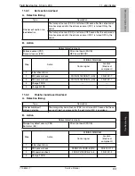
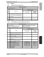
Finisher staple misfeed

A. Detection timing

B. Action

10

.3.7

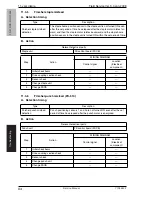
Finisher punch misfeed (PK-515)

A. Detection timing

B. Action

Type

Description

Finisher staple misfeed 
detection

The staple home position sensor in the staple unit is not turned ON even
after the set period of time has elapsed after the staple motor rotates for-
ward, and then the staple motor rotates backward, and the staple home 
position sensor in the staple unit is turned ON within the set period of time.

Relevant electrical parts

Staple unit

FS control board (FSCB)

Step

Action

WIRING DIAGRAM

Control signal

Location

(Electrical 

component)

1

Initial check items

2

Drive coupling section check

3

Sensor check

4

Change staple unit

5

Change FSCB

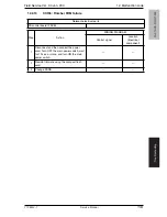
Type

Description

Finisher punch misfeed 
detection

Punch positioning sensors 1 and 2 are not turned ON even after the set 
period of time has elapsed after the punch motor is energized.

Relevant electrical parts

Punch unit

FS control board (FSCB)

Step

Action

WIRING DIAGRAM

Control signal

Location

(Electrical 

component)

1

Initial check items

2

Drive coupling section check

3

Sensor check

4

Change punch unit

5

Change FSCB

         Service Manual                                                       Y10

8442-7

Содержание FS-519

Страница 1: ...FS 519 PK 515 OT 602 Option Printer SERVICE MANUAL Code Y108442 7 d Color MF201Plus MF250 MF350 d Color MF450...

Страница 2: ...PUBLICATION ISSUED BY Olivetti S p A 77 Via Jervis 10015 Ivrea TO Italy Copyright 2008 Olivetti All rights reserved...

Страница 3: ...cover film 17 3 1 4 Cleaning of the rollers and rolls 20 3 1 5 Cleaning of the paddles 22 4 Other 23 4 1 Disassembly adjustment prohibited items 23 4 2 Precautions to be observed when option configura...

Страница 4: ...Shutter drive gear 63 4 4 23 Duplex guide solenoid 64 4 4 24 FS control board 66 Adjustment Setting 5 How to use the adjustment section 67 6 Sensor Check for d Color MF350 Family 68 6 1 Check procedu...

Страница 5: ...motor unit failure 101 12 2 11 C1301 Finishing option cooling fan motor failure 102 12 2 12 C1402 FNS nonvolatile memory failure 102 12 2 13 CC155 Finisher ROM failure 103 10 3 Solution 85 10 3 1 Ini...

Страница 6: ...FS 519 PK 515 OT 602 General Maintenance Adjustment Setting Troubleshooting Field Service Ver 3 0 Jan 2008 iv Blank Page...

Страница 7: ...5S A5 B5S B5 B6S A4S A4 B4 A3 A3Wide 5 1 2 x 8 1 2S 5 1 2 x 8 1 2 8 1 2 x 11S 8 1 2 x 11 8 1 2 x 14 11 x 17 12 1 4 x 18 Max 311 15 mm x 457 2 mm 12 25 x 18 inch Min 90 mm x 139 7 mm 3 5 x 5 5 inch 60...

Страница 8: ...11S or less 1000 sheets B4 8 1 2 x 14 or greater 500 sheets Thick paper 91 to 271 g m2 24 25 to 72 lb Type Size Weight Max capacity No of sheets to be stapled Plain paper Recycled paper A5 B5S B5 A4S...

Страница 9: ...17 Front of the corner 30 degree Back of the corner Parallel A4S B5S A5 8 1 2 x 11S 8 1 2 x 14 Front of the corner Parallel Side Parallel 2 point A4S A4 A3 B5S B5 B4 A5 8 1 2 x 11S 8 1 2 x 11 8 1 2 x...

Страница 10: ...3 Paper type Plain paper 60 to 209 g m2 16 to 55 5 lb Thick paper 1 2 3 91 to 256 g m2 24 25 to 68 lb Punch hole Metric 2 holes 4 holes Inch 2 3 hole Sweden 4 holes Number of stored punch wastes Metri...

Страница 11: ...5 5 inch Plain paper 60 to 90 g m2 16 to 24 lb 200 sheets up to a height of 24 mm Recycled paper Special Government standard postcards Envelope OHP transparencies Translucent paper Label Thick paper...

Страница 12: ...ions D Operating environment Conforms to the operating environment of the main body NOTE How product names appear in the document FS 519 Finisher PK 515 Punch kit OT 602 Output tray Dimensions 282 mm...

Страница 13: ...e 5 1 2 x 8 1 2S 5 1 2 x 8 1 2 8 1 2 x 11S 8 1 2 x 11 8 1 2 x 14 11 x 17 12 1 4 x 18 Max 311 15 mm x 457 2 mm 12 25 x 18 inch Min 90 mm x 139 7 mm 3 5 x 5 5 inch 64 to 90 g m2 17 to 24 lb Exit tray1 2...

Страница 14: ...less 1000 sheets B4 8 1 2 x 14 or greater 500 sheets Thick paper 91 to 300 g m2 24 25 to 79 75 lb Type Size Weight Max capacity No of sheets to be stapled Plain paper Recycled paper A5 B5S B5 A4S A4 B...

Страница 15: ...1 2 x 11 11 x 17 Front of the corner 30 degree Back of the corner Parallel A4S B5S A5 8 1 2 x 11S 8 1 2 x 14 Front of the corner Parallel Side Parallel 2 point A4S A4 A3 B5S B5 B4 A5 8 1 2 x 11S 8 1...

Страница 16: ...weden B5S A4 B4 A3 Paper type Plain Paper Recycled paper 64 to 209 g m2 17 to 55 5 lb Punch hole Metric 2 holes 4 holes Inch 2 3 hole Sweden 4 holes Number of stored punch wastes Metric 2 holes For 2...

Страница 17: ...Special Government standard postcards 20 sheets Envelope OHP transparencies Translucent paper Label Letterhead Thick paper 1 91 to 120 g m2 24 25 to 32 lb Thick paper 1 121 to 157 g m2 32 25 to 41 75...

Страница 18: ...tions D Operating environment Conforms to the operating environment of the main body NOTE How product names appear in the document FS 519 Finisher PK 510 Punch kit OT 602 Output tray Dimensions 282 mm...

Страница 19: ...g procedure of maintenance represents the isopropyl alcohol 3 1 1 Replacing the paddles A Periodically replaced parts cycle Paddles Every 800 000 prints B Procedure 1 Remove the tray unit See P 31 2 R...

Страница 20: ...ered with transparent film 2 to their original position If there is difficulty in installing the paddles apply alcohol to the root of the paddles and install them 6 Install the paddle holder assy 1 NO...

Страница 21: ...press the paddle so that it is fixed without any tilt For proper set screw tightening to fix the paddle turn each set screw only one quarter 1 4 of a turn after the set screw tip has reached the shaf...

Страница 22: ...he cleaning pad A Periodically replaced parts cycle Cleaning pad Every 800 000 prints B Procedure 1 Remove the tray unit See P 31 2 Remove the finisher unit See P 34 3 Remove the screw 1 and remove th...

Страница 23: ...ly lubricated parts cycle Worm gear Every 800 000 prints B Periodically replaced parts cycle Cover film Every 800 000 prints C Procedure NOTE Before the following lubrication and replacement work make...

Страница 24: ...r motor assy 2 NOTE Remove the elevator motor assy while holding the lower part of the tray 3 with your hand NOTE Before reinstalling the elevator motor assy raise the tray 3 until the lever 1 attache...

Страница 25: ...new cover film clean the metal surface where the new cover film is attached Align the right ends of the new cover film and the metal as shown in the illustration 7 Apply the following grease to the w...

Страница 26: ...Procedure 1 Remove the tray unit See P 31 2 Remove the finisher unit See P 34 3 Remove the finisher unit upper cover See P 27 4 While turning processing knob FN5 1 wipe the roller and roll 2 using a...

Страница 27: ...installed 7 Lower processing guide FN3 1 8 While turning processing knob FN2 2 wipe the roll 3 using a soft cloth dampened with alcohol 9 Upper processing guide FN1 1 10 While turning processing knob...

Страница 28: ...hol 3 1 5 Cleaning of the paddles A Periodically cleaning parts cycle Paddles Every 300 000 prints B Procedure 1 Remove the tray unit See P 31 2 Remove the finisher unit See P 34 3 Using a soft cloth...

Страница 29: ...to prevent them from being removed by mistake Do not remove or loosen any of the red painted screws in the field It should also be noted that when two or more screws are used for a single part only on...

Страница 30: ...Do not move the screw by using the adjust plate 2 B When OT 602 MT 502 or OT 602 SD 505 are mounted 1 Loosen two screws 1 and move them in the direction of the arrow Then tighten them at the corre sp...

Страница 31: ...1 Tray 1 12 Tray 2 13 Output tray OT 602 Option 14 Units Tray unit 15 Finisher unit 16 Stapler unit 17 Punch kit PK 510 515 Option 18 Electric parts Exit roller motor 19 Elevator motor 20 Duplex guide...

Страница 32: ...llation first fit the tab 3 into position 4 4 2 Finisher unit left front cover 1 Remove the front door See P 27 2 Remove two screws 1 and remove the finisher unit left front cover 2 4 4 3 Finisher uni...

Страница 33: ...ee P 34 3 Remove the finisher unit rear cover See P 26 4 Remove three screws 1 and remove the finisher unit upper cover 2 4 4 5 Front door 1 Open the front door 1 2 Remove the screw 2 and the retain i...

Страница 34: ...upper cover See P 27 4 Remove the harness bundle 1 from three harness guides 2 5 Remove the screw 1 and tab 2 and remove the harness guide 3 6 Remove the screw 1 and the ground wire 7 Remove the wire...

Страница 35: ...racket 3 and the intake cover 4 4 4 8 Tray unit front cover Tray unit rear cover Connector cover 1 Remove four screws 1 and remove the tray unit front cover 2 2 Remove two screws 3 and remove the tray...

Страница 36: ...enance 4 4 9 Tray 1 Tray 2 1 Remove two screws 1 and remove the tray 1 2 2 Remove two screws 3 and remove the tray 2 4 4 4 10 Output tray OT 602 Option 1 Remove two screws 1 and remove the output tray...

Страница 37: ...n If the exit tray OT 602 is installed remove it in advance See P 30 1 Remove the front door See P 27 2 Remove two screws 1 and remove the tray unit upper cover 2 3 Remove two screws 1 and remove the...

Страница 38: ...remove the screw 2 and the ground wire 6 Remove two shoulder screws 1 NOTE When the output tray OT 602 is mounted remove the screw 2 and remove the mounting holder 3 7 Remove the screw 1 and the stop...

Страница 39: ...PK 510 OT 602 Maintenance 8 Position the stopper 2 as shown and secure it with the screw 1 9 Remove two screws 1 and remove the mounting bracket 2 10 Remove four screws 1 A01GF2C509DA 1 2 A01GF2C510D...

Страница 40: ...lor MF350 Family 4 4 12 Finisher unit 1 Remove the tray unit See P 31 P 25 d Color MF450 A01GF2C513DA 1 2 Disconnect the hookup cord 1 3 Hold the positions as shown in the illustration to remove the f...

Страница 41: ...r MF250 d Color MF201Plus Maintenance 1 Remove four covers 5 while remov ing four latches 1 2 3 and 4 2 Remove seven screws 1 to remove the upper unit rear for the stand table 2 3 Remove five screws 1...

Страница 42: ...mounting plate 2 5 Remove eight screws 1 to remove two supports 2 6 Set the mounting plate 1 which was removed in step 4 and tighten two screws 2 NOTE Use cares since the length of these screws are d...

Страница 43: ...ews shown on the illustration are different from other screws 8 Mount the stand table upper unit rear 1 which was removed in step 2 and tighten seven screws 2 NOTE Use care since the lengths of the sc...

Страница 44: ...our adjusting plates 1 fur nished with the main body 11 Remove four screws 1 and remove the lower unit for the stand table 2 12 Mount the stand table 1 to the main body and tighten it with four screws...

Страница 45: ...s removed in step 11 and tighten four screws 2 14 Mount two covers 1 which were removed in step 1 15 Adjust the adjusting plate 1 to touches the floor NOTE When the height of the setting table is chan...

Страница 46: ...m 2 Following adjustment is necessary when the width does not fall within the specifications 3 Pull the lever to unlock it and remove the tray unit from the main body 4 Remove two covers 1 from the le...

Страница 47: ...back side NOTE To measure the front side open the front door and measure it using fin isher side as supporting point refer ring showed on the illustration left 7 When the value does not fall within th...

Страница 48: ...and back side Specifications 4 2 mm 2 If X is out of the specified range remove two covers 1 from the legs of the stand table 3 Loosen four screws 1 two screws each for the left and right and adjust...

Страница 49: ...he front side open the front door and measure it using fin isher side as supporting point refer ring showed on the illustration left 5 When the value does not fall within the specified range remove th...

Страница 50: ...n the dial 1 and move the sta pler forward 3 Remove the staple cartridge 4 Remove the screw 2 and remove the cover 3 5 Remove the screw 1 6 Remove the screw 1 and remove the ground wire 7 Disconnect t...

Страница 51: ...er unit upper cover See P 27 4 Remove the finisher unit right front cover See P 26 5 Remove the edge cover 1 and dis connect two connectors 2 NOTE When the creasing unit is mounted remove two screws 1...

Страница 52: ...the tray unit See P 31 2 Remove the finisher unit See P 34 3 Remove the finisher unit left front cover See P 26 4 Remove eleven wire saddles 1 and remove the edge cover 2 5 Disconnect three connector...

Страница 53: ...storage paddle drive clutch assy 2 NOTE When installing the storage paddle drive clutch insert the hexagonal wrench into the flame notch 1 and confirm that the storage paddle drive axis 2 fits to the...

Страница 54: ...sition as shown in the illustra tion Specifications A 3 3 3 mm NOTE When installing the storage paddle drive clutch adjust the distance between the E ring 1 and the stor age paddle drive clutch gear 2...

Страница 55: ...4 Other 49 10 Remove two C rings 1 and two bushings 2 11 Remove four screws 1 and remove the exit transportation section upper assy 2 9J08F2C545DA 1 1 2 2 9J08F2C546DA 1 2 1 FS 519 PK 515 OT 602 Maint...

Страница 56: ...earings 2 and remove the exit upper roller assy 3 13 Remove the C ring 1 and the bush ing 2 and remove the storage pad dle assy 3 14 Remove the storage paddle 1 9J08F2C547DA 1 1 2 3 2 9J08F2C529DA 2 1...

Страница 57: ...r unit See P 34 3 Remove the finisher unit left front cover See P 26 4 Remove the gear 1 and the bushing 2 5 Remove the C ring 3 and the bush ing 4 6 Remove the exit paddle drive clutch assy 5 7 Loose...

Страница 58: ...tch turn up the side that the distance between tabs is wider and hook the solenoid flapper 1 on the tab 2 NOTE When installing the exit paddle drive clutch assy adjust the dis tance between the bushin...

Страница 59: ...the posi tion of blocked panel 1 Specifications A 14 6 1 mm When installing the exit lower roller assy adjust the position of the arm holder 2 Specifications B 56 4 3 mm 11 Disassemble the exit lower...

Страница 60: ...cover See P 27 4 Remove the exit transportation section upper assy See P 38 5 Remove the exit lower roller assy See P 46 6 Remove two screws 1 and remove the ground wire 7 Remove two screws 2 8 Remove...

Страница 61: ...saddle 1 and dis connect two connectors 2 11 Remove the ground wire from the harness guide 3 12 Remove the harness bundle 1 from the harness guide 2 13 Remove the screw 1 and tab 2 and remove the har...

Страница 62: ...ve two gears 2 15 Remove three screws 1 and bush ing 2 and remove the gear assy 3 NOTE When installing the gear assy fit the mounting plate 1 to the caulk ing axis 2 and tightening with screw Make sur...

Страница 63: ...vator motor Timing belt A Removal procedure 1 Remove the tray unit See P 31 2 Remove the tray unit front cover See P 29 3 Remove the tray unit rear cover See P 29 4 Remove the screw 1 and remove the g...

Страница 64: ...T 602 Maintenance 6 Remove three screws 1 and remove the elevator motor assy 2 7 Remove the C ring 1 and remove the gear cover 2 8 Remove two screws 1 and remove the metal bracket 2 A01GF2C534DA 1 2 A...

Страница 65: ...er rear 2 and belt 3 10 Remove two screws 1 and remove elevator mounting plate rear 2 11 Remove two screws 1 and remove the belt holder 2 12 Remove the timing belt rear 3 NOTE When installing the timi...

Страница 66: ...aintenance 13 Remove the lever 1 14 Remove the C ring 1 and pin 2 and remove the gear lower front 3 NOTE Use care not to lose the pin 15 Remove two screws 1 and remove the metal bracket 2 1 9J08F2C023...

Страница 67: ...ove the C ring 1 and remove the gear upper front 2 17 Remove two screws 1 and remove elevator mounting plate front 2 18 Remove two screws 1 and remove the belt holder 2 19 Remove the timing belt front...

Страница 68: ...motor assy NOTE Fit the hole of the elevator mount ing plate front back 1 and the hole of the elevator tray 2 and install them by fixing the front and back along 2 Fit the blocked plate 1 as shown in...

Страница 69: ...29 3 Remove the tray unit rear cover See P 29 4 Remove four screws 1 and remove the shutter drive gear assy 2 5 Remove two C rings 1 and remove the gear 1 2 gear 2 3 and gear 3 4 NOTE When installing...

Страница 70: ...the finisher unit rear cover See P 26 3 Remove the finisher unit upper cover See P 27 4 Remove two saddles 1 and discon nect the connector 2 5 Remove the screw 1 and remove the duplex guide solenoid 2...

Страница 71: ...wn until the space A reaches specification and tighten the screw 1 Specification 3 5 mm Tolerance 0 5 mm NOTE The switch tab 2 shall face down and touch to the lever 3 3 Lift down the plunger 1 and ma...

Страница 72: ...4 FS control board 1 Remove the tray unit See P 31 2 Remove four screws 1 and remove the cover 2 3 Disconnect all the connectors on the FS control board 4 Remove four board supports 1 and remove the F...

Страница 73: ...sunlight ventilation etc levelness of the installation site The original has a problem that may cause a defective image The density is properly selected The original glass slit glass or related part...

Страница 74: ...k procedure A Procedure 1 Call the Service Mode to the screen See P 338 of the main body service manual 2 Touch State Confirmation 3 Touch Sensor Check 4 Touch two times z 6 1 1 Sensor check screen Th...

Страница 75: ...Blocked Unblocked Elevate Tray Proliferation Short connector Set Not set PS11 Elevate Position Elevator tray home position sensor Blocked Unblocked PS14 Home Shutter Shutter home position sensor Bloc...

Страница 76: ...checked on the panel with the main body in the standby state including a misfeed malfunction and closure failure condition A Procedure 1 Call the Service Mode to the screen See P 434 of the main body...

Страница 77: ...d Unblocked Elevate Tray Proliferation Short connector Set Not set PS11 Elevate Position Elevator tray home position sensor Blocked Unblocked PS14 Home Shutter Shutter home position sensor Blocked Unb...

Страница 78: ...position to the inner 2 point stapling position for A4 o Moves from the starting position and stops after the predetermined time o Moves to the front of A4 o Moves from the starting position and stops...

Страница 79: ...2Holes appears only when the punch kit PK 515 is installed The punch is driven once at a 2holes o The operation is finished 7 Outlet Open Close Opens and closes the exit o The exit opens o Stops after...

Страница 80: ...ently occurs in punch hole mode 1 Call the Service Mode to the screen See P 338 of the main body service manual 2 Touch Finisher 3 Touch CB FN adjustment 4 Touch Punch Regist Loop Size 5 Set the corre...

Страница 81: ...ified range perform the follow ing procedure to punch hole position adjustment 4 Call the Service Mode to the screen 5 Touch Finisher 6 Touch CB FN adjustment 7 Touch Punch Horizontal Position 8 Set t...

Страница 82: ...e by the punch kit installed Use Use when the punch kit is installed Setting Procedure The default setting is Non installat 1 Touch PK 510 if installed on MF450 and PK 515 if installed on MF350 Family...

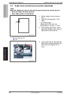
Страница 83: ...make a 1 sided copy from a 1 sided original 2 Fold the output paper in half and check whether the punch hole posi tions are aligned Specification 0 2 mm 3 If the punch hole position is mis aligned adj...

Страница 84: ...per width 182 to 216 mm 2 point staple Y paper width X 11 2 X A3 A4 137 B4 B5 114 A4S 190 B5S 162 Substitute above into the equation 3 If the staple position is misaligned adjust with the following pr...

Страница 85: ...r 5 Turn the dial 1 and move the sta pler forward 6 Loosen the screw 2 and remove the cover 3 7 Loosen two adjustment screws 1 and move the stapler unit 2 in the direction of the arrow to make the adj...

Страница 86: ...position is misaligned 1 Set the staple mode and make a copy 2 Check the staple position of the paper 1 point tilted staple Paper width 216 to 297 mm Specification A 6 5 mm 1 5 mm 3 If the staple pos...

Страница 87: ...ails to move appropriately 1 Check the clearance between the stapler unit 1 and the FD stopper 2 is within the specified range Specification A 2 0 mm 0 5 mm 2 If the value does not fall within the spe...

Страница 88: ...9 Mechanical adjustmen Field Service Ver 3 0 Jan 2008 82 FS 519 PK 515 OT 602 Adjustment Setting Blank Page Service Manual Y108442 7...

Страница 89: ...achine 10 1 1 Misfeed display resetting procedure Open the corresponding door clear the sheet of paper misfed and close the door Display Code Misfeed location Misfeed processing location Action 1 7218...

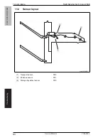
Страница 90: ...Field Service Ver 3 0 Jan 2008 84 FS 519 PK 515 OT 602 Troubleshooting 10 2 Sensor layout 1 Transport sensor PS2 2 Entrance sensor PS1 3 Storage tray detect sensor PS3 9J08F4C501DA 1 2 3 Service Manu...

Страница 91: ...1 Turn over the stacked paper in the paper tray OK NG Go to step 2 2 Does paper curl occur just after a warm up has been completed or the sleep mode has been turned OFF YES Go to step 3 Does paper cu...

Страница 92: ...t section misfeed detection The entrance sensor PS1 is turned ON when the power switch is set to ON a door or cover is opened and closed or a misfeed or malfunction is reset The transport sensor PS2 i...

Страница 93: ...t sensor PS2 FS control board FSCB MFP board MFPB Step Action WIRING DIAGRAM Control signal Location Electrical component 1 Initial check items 2 PS1 I O check sensor check FSCB PJ19 11 ON FS 519 C 7...

Страница 94: ...turned ON within the set period of time Relevant electrical parts Staple unit FS control board FSCB Step Action WIRING DIAGRAM Control signal Location Electrical component 1 Initial check items 2 Driv...

Страница 95: ...1 1 1 Misfeed display resetting procedure Open the corresponding door clear the sheet of paper misfed and close the door Display Code Misfeed location Misfeed processing location Action 1 7218 Finishe...

Страница 96: ...Field Service Ver 3 0 Jan 2008 90 FS 519 PK 510 OT 602 Troubleshooting 11 2 Sensor layout 1 Transport sensor PS2 2 Entrance sensor PS1 3 Storage tray detect sensor PS3 9J08F4C501DA 1 2 3 Service Manu...

Страница 97: ...Change the paper Instruct the user in correct paper storage Is a foreign object present along the paper path or is the paper path deformed or worn Clean or change the paper path Are the rolls rollers...

Страница 98: ...n misfeed detection The entrance sensor PS1 is turned ON when the power switch is set to ON a door or cover is opened and closed or a misfeed or malfunction is reset The transport sensor PS2 is turned...

Страница 99: ...ransport sensor PS2 FS control board FSCB MFP board MFPB Step Action WIRING DIAGRAM Control signal Location Electrical component 1 Initial check items 2 PS1 sensor check FSCB PJ19FSCB 11 ON FS 519 C 7...

Страница 100: ...turned ON within the set period of time Relevant electrical parts Staple unit FS control board FSCB Step Action WIRING DIAGRAM Control signal Location Electrical component 1 Initial check items 2 Driv...

Страница 101: ...lure The alignment home position sensor 1 PS7 is not turned ON even after the set period of time has elapsed after the main power switch is set to ON The alignment home position sensor 1 PS7 is not tu...

Страница 102: ...lure The home position sensor is not turned ON even after the set period of time has elapsed after the staple motor is energized beginning of staple operation C11C0 Punch cam motor unit failure The pu...

Страница 103: ...sensor PS11 Elevator tray lower limit sensor PS13 Elevator top face detection sensor PS12 Relay board 1 REYB 1 FS control board FSCB Step Action WIRING DIAGRAM Control signal Location Electrical comp...

Страница 104: ...onent 1 Check the M5 connector for proper con nection and correct as necessary 2 Check M5 for proper drive coupling and correct as necessary 3 M5 operation check FSCB PJ11 1 to 4 FS 519 C 10 4 PS7 I O...

Страница 105: ...ction and correct as necessary 2 PS6 I O check sensor check FSCB PJ13 11 ON FS 519 C 4 3 SD2 operation check FSCB PJ13 2 REM FS 519 C 5 4 Change FSCB Relevant electrical parts Exit roller motor M10 Ex...

Страница 106: ...ary 3 M8 operation check FSCB PJ6 7 to 8 FS 519 J 5 4 PS14 I O check sensor check FSCB PJ18 5 ON FS 519 J 5 5 Change REYB 1 6 Change FSCB Relevant electrical parts Stapling unit moving motor M7 Staple...

Страница 107: ...nnection and correct as neces sary 2 Check the staple unit for proper drive coupling and correct as necessary 3 Staple unit operation check 4 Change staple unit 5 Change FSCB Relevant electrical parts...

Страница 108: ...n nection and correct as necessary 2 Check FM9 for proper drive coupling and correct as necessary 3 Check the FSCB connectors for proper con nection and correct as necessary 4 FM9 operation check FSCB...

Страница 109: ...t electrical parts FS control board FSCB Step Action WIRING DIAGRAM Control signal Location Electrical component 1 Disconnect and then connect the power cord Turn OFF the main power switch wait for 10...

Страница 110: ...12 Malfunction cod Field Service Ver 3 0 Jan 2008 104 FS 519 PK 515 OT 602 Troubleshooting Blank Page Service Manual Y108442 7...

Страница 111: ...UPDATING STATUS DATE UPDATED PAGES PAGES CODE 10 2008 1ST EDITION 111 Y108442 7...

Отзывы: