7-72
687200Q
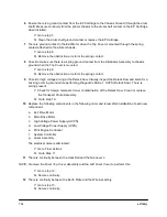
7.4.26 Mechanical Noise
You were directed to this RAP to diagnose and repair an audible mechanical noise coming from within
the printer. Please be aware that electrical arcing may also generate an audible noise, especially in the
areas of the High Voltage Power Supply and the line voltage.
1 The noise is present in the standby mode.
Y: Power OFF the printer and perform the following checks. Repair/replace any faulty
component:
• Inspect the Fan Assembly and any associated wire harness.
• Inspect the Laser Assembly.
• Inspect/remove the Hard Drive Assembly mounted on the System Controller. After
removal, test again in the standby mode to determine if the Hard Drive is the source of
the noise.
N: Go to step 2.
2 Execute Diagnostic Mode 1, Main Motor. The noise is present.
Y: Go to step 3.
N: Go to step 5.
3 Open the Front Cover Assembly and remove the EP Cartridge. Remember to bypass the
interlocks for the Front Cover Assembly and the EP Cartridge. Perform Diagnostic Mode 1, Main
Motor and inspect the drive train gears for broken or missing teeth. The noise is present.
Y: Go to step 4.
N: Inspect the Front Cover Assembly for loose, broken, or misaligned parts. Replace the EP
Cartridge if necessary.
4 Open the Rear Cover, remove the Fuser Assembly, and bypass the Rear Cover interlock. While
performing Diagnostic Mode 1, Main Motor, inspect the drive train gears from the rear of the
printer for broken or missing teeth. The noise is present.
Y: Carefully inspect/repair the Paper Handling Unit for the source of the noise before
replacing the Main Motor Assembly.
N: Replace the Fuser Assembly.
5 Perform Diagnostic Mode 1 (Exit Motor CW and CCW respectively). The noise is present.
Y: Determine the exit component causing the noise and replace.
N: Go to step 6.
6 Power OFF the printer. Remove all the interlock bypasses in steps 3 and 4, and install the EP
Cartridge. Remove all input and output options, and the Hard Disk from the System Controller.
Close the Front and Rear Cover Assemblies. Power ON the printer, and from Diagnostic Mode 2
(Test Print Mode), run a Print Engine Controller Test Print. The noise is present.
Y: Inspect the Tray 1 Feed Roll drive components and replace as necessary.
N: Go to step 7.
Содержание DR N17
Страница 1: ...DVHU 3ULQWHU 3 1 6HUYLFH 0DQXDO Code 687200Q 00 September 1999...
Страница 3: ......
Страница 6: ...iv 687200Q 1 2...
Страница 8: ...vi 687200Q This page intentionally blank...
Страница 12: ...687200Q Service Manual 1 2...
Страница 16: ...2 2 687200Q...
Страница 24: ...3 2 687200Q...
Страница 26: ...3 4 687200Q PL 1 Covers I S S 2 1 S S 6 S KL S 3 5 S S S 4 S S SAS301FA...
Страница 28: ...3 6 687200Q PL2 Covers II wsm3 07 7 8 13 4 3 2 5 9 11 S 1 with 2 11 12 6 10 SAS302FE...
Страница 30: ...3 8 687200Q PL 3 Paper Tray 3 2 7 6 5 4 8 S S S 1 with 2 S S SAS303FB...
Страница 32: ...3 10 687200Q PL 4 Paper Transportation I...
Страница 36: ...3 14 687200Q PL 6 Paper Transportation III 2 S S S S 1 1 with 2 S SAS306FC...
Страница 44: ...3 22 687200Q PL 10 Electrical Module I with Top Cover 2 4 3 S S 1 SAS310FB 5...
Страница 48: ...3 26 687200Q 3 2 6 4 5 1 PL 12 System Controller...
Страница 54: ...4 4 687200Q...
Страница 173: ...687200Q Service Manual 5 61 Figure 5 2 2 1 IOT Test Print Lead Edge Inboard Edge 4 mm 4 mm 1003...
Страница 190: ...5 78 687200Q This page intentionally left...
Страница 193: ...687200Q Service Manual 5 81 Figure 5 5 1 2 Printer Data Label and Serial Number Plate...
Страница 196: ...6 2 687200Q...
Страница 206: ...6 12 687200Q This page intentionally blank...
Страница 210: ...6 16 687200Q This page intentionally blank...
Страница 232: ...6 38 687200Q 13 MCU MAIN MOTOR 1 2 3 4 5 6 P J14 MAIN MOT ON MOT READY 24V 24V RTN MCU MAIN MOT M...
Страница 234: ...6 40 687200Q 14 MCU FAN MOTOR 1 2 3 4 P J23 24V RTN FAN READY 24V FAN FAN FAST MCU FAN M SAS619XA...
Страница 236: ...6 42 687200Q 15 MCU EXIT MOTOR 1 2 3 4 5 6 P J24 24V A COM A A 24V B COM B B MCU EXIT MOT M SAS620F...
Страница 243: ...687200Q Service Manual 6 49 This page intentionally blank...
Страница 248: ...6 54 687200Q Notes...
Страница 252: ...7 4 687200Q...
Страница 262: ...7 14 687200Q This page intentionally blank...
Страница 366: ...8 4 687200Q Figure 8 1 1 1 2 Paper Tray SAS214F...
Страница 369: ...687200Q Service Manual 8 7 Figure 8 1 3 1 2 Tray W D H SAS217F...
Страница 394: ...8 32 687200Q 8 7 4 P216 Pin Layout Refer to the P216 Pin Layout when troubleshooting the 500 Sheet Paper Feeder option...
Страница 421: ...687200Q Service Manual 9 21 Replacement Perform the removal steps in reverse order...
Страница 442: ...9 42 687200Q 9 8 Installation and Removal For the installation and removal of the OCT Unit see the Printer User Guide...
Страница 447: ...687200Q Service Manual 10 5 This page intentionally blank...
Страница 476: ...10 34 687200Q Notes...
Страница 492: ...11 16 687200Q Figure 11 3 7 1 Top Cover Removal FRONT 1 2 3 4 J230 J230 J231 J231 SAS4CAFA...
Страница 510: ...11 34 687200Q 11 7 Wiring Diagrams 11 7 1 Connector Locator J 1 3 5 1 11 1 13 1 15 J231 J201 J230 SAS641FA...
Страница 518: ...Spare parts catalogue 687200Q DP N17 WITH OPTION SPARE PARTS CATALOGUE FROM SERVICE MANUAL 1...
Страница 521: ...3 4 687200Q PL 1 Covers I S S 2 1 S S 6 S KL S 3 5 S S S 4 S S SAS301FA...
Страница 523: ...3 6 687200Q PL2 Covers II wsm3 07 7 8 13 4 3 2 5 9 11 S 1 with 2 11 12 6 10 SAS302FE...
Страница 525: ...3 8 687200Q PL 3 Paper Tray 3 2 7 6 5 4 8 S S S 1 with 2 S S SAS303FB...
Страница 527: ...3 10 687200Q PL 4 Paper Transportation I...
Страница 531: ...3 14 687200Q PL 6 Paper Transportation III 2 S S S S 1 1 with 2 S SAS306FC...
Страница 539: ...3 22 687200Q PL 10 Electrical Module I with Top Cover 2 4 3 S S 1 SAS310FB 5...
Страница 543: ...3 26 687200Q 3 2 6 4 5 1 PL 12 System Controller...
Страница 555: ......
Страница 556: ...Spare parts catalogue 687200Q A 1 GENERAL CODES INDEX DP N17...


