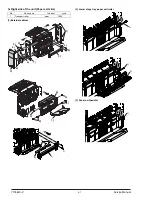
Olivetti AR-FN6 Скачать руководство пользователя страница 28


10-1

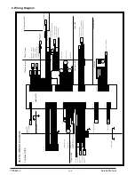
[10] BLOCK DIAGRAM, WIRING DIAGRAM
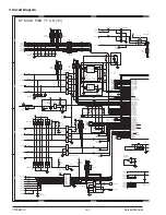
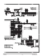
1. Block Diagram

Staple Unit Motor

AR-FN6

Elevator Motor

Paper Push Solenoid

Staple Compiler Gate Solenoid

Finisher Gate Solenoid

Tray2 Solenoid

Stopper Solenoid

Staple unit Turn Motor

Pushher Motor

4

Jogger Front Motor

Jogger Rear Motor

Pushher Home Position sensor

Staple Compiler Paper Detect sensor

Jogger Front Home Position sensor

Tray1 Paper Full detect sensor

Staple Turn Home Position sensor2

Paper In Detect sensor

Paper Out Detect sensor

Tray2 Down detect sensor

Staple Compiler In Detect sensor2

Staple Compiler In Detect sensor

Staple Turn Home Position sensor1

Tray2 Upper detect sensor

Jogger Rear Home Position sensor

Tray2 Output Motor

Main Motor

Stapler No Cartridge sensor

Stapler Home Position sensor

Stapler Self Priming sensor   

Stapler Low Staple sensor

Stapler Motor

Stapler

Tray2 Paper Detect sensor

Door SWitch 1

AR-DC1

Staple Compiler Rolor Solenoid

Paper Push Detect sensor

Door Open Detect sensor

(74HC151)

(74HC151)

(MTD1361F)

(MTD1361F)

(MTD1361F)

(MTD1361F)

4

JFM

+24V

4

4

JRM

+24V

4

4

(MTD1361)

4

+24V

PSM

4

4

STUM

+24V

+24V

T2OM

4

MM

+24V1

2

2

CPU

(uPD784214AGC)

(STA457C)

2

EVM

2

STTM

2

2

(2SB1198K x4)

+24V

SCGS

PPS

+24V

+24V

SPS

T2S

+24V

SCRS

+24V

FGS

+24V

(TD62003AP)

GND1

GND2

FG

3

3

2

A ~ C

A ~ C

P70 ~ P72

Y

Y

SEL0 ~ SEL2

T1PF

+5V

(1-B3)

(1-D3)

DSW1

DSW2

Door SWitch 2

SCPD

+5V

+5V

PPD

JRHP

+5V

+5V

JFHP

T2PD

+5V

+5V

T2UP

T2DN

+5V

+5V

POD

SCID2

+5V

+5V

PID

SCID

+5V

PSHP

+5V

+5V

STTHP2

+5V

+5V

DOPD

(1-D3)

STTHP1

A8 ~ A16

AD0 ~ AD7

LATCH

EPROM 1M

(74HC373)

LE

A8 ~ A16

A0 ~ A7

D0 ~ D7

(M27C1001)

OE

A8 ~ A16

AD0 ~ AD7

A0 ~ A7

STM

STHP

STNC

STLS

STUHP

Staple Unit Home Position sensor

(1-B3)

STSP

+5V

(2SB1198K x4)

+5V

AR-FN6 BLOCK DIAGRAM

P80 ~ 83

P84 ~ 87

P131

RTP4 ~ RTP7

P00

P30 ~ 33

P132

P130

RTP0 ~ RTP7

P102

P103

P100,101

P92,93

P90,91

P24

P25

P26

P27

P94

/RESET

P22

P23

TXD1

RXD1

P16

D7

D1

D2

P17

D6

D5

D4

D2

INTP2

INTP4

INTP5

P12

P11

P15

P14

P13

P36

P10

P35

P34

D1

D3

P01

RD

ASTB

P37

INTP3

D0

JPD

PSPD

STUPD

T2OPD

MME

MMCK

FGS-FIN2/

RES-FIN2

DTR-FIN2/

DSR-FIN2/

TXD-FIN2

RXD-FIN2

IN0

DSW1

DSW2

24VM

IN1

RD

ASTB

+5V

+24V

+24V

+24V1

+24V2

+24V2

+24V2

STNC

STSP

STSP

STLS

MMLK

STLS

STNC

MMLK

A

A

B

B

C

C

D

D

E

E

4

4

3

3

2

2

1

1

T

ransistor

arr

a

y

(Option po

w

er)

Main PWB

Input b

uff

er

Input b

uff

er

Input b

uff

er

Multiple

x

er 1

Multiple

x

er 2

+24V

monitor

(le

vel

con

ver

ter)

circuit

Input b

uff

er

Input b

uff

er

Input b

uff

er

Input b

uff

er

Output b

uff

er

Output b

uff

er

Input b

uff

er

Chopping

circuit

Chopping

circuit

Chopping

circuit

Chopping

circuit

Chopping

circuit

Output b

uff

er

Output b

uff

er

H br

idge

circuit

H br

idge

circuit

H br

idge

circuit

     "# $%&'()

Y105

620

-

2


  Service Manual

Содержание AR-FN6

Страница 1: ...AR FN6 SERVICE MANUAL Code Y105620 2 Options...

Страница 2: ...PUBLICATION ISSUED BY Olivetti S p A 77 Via Jervis 10015 Ivrea TO Italy Copyright 2006 Olivetti All rights reserved...

Страница 3: ...4 UNPACKING AND INSTALLATION 4 1 5 EXTERNAL VIEWS AND INTERNAL STRUCTURES 5 1 6 MACHINE OPERATION 6 1 7 OPERATIONAL DESCRIPTIONS 7 1 8 ADJUSTMENTS 8 1 9 DISASSEMBLY AND ASSEMBLY MAINTENANCE 9 1 10 BL...

Страница 4: ...Finisher Any of the units must be installed together Multi purpose drawer Stand 3 x 500 sheet paper drawer Stand MPD 2000 sheet Duplex module bypass tray Duplex module B W scanner module DSPF Saddle s...

Страница 5: ...ray full detection Upper tray Provided Lower tray Provided Power consumption Less than about 67 3W Power source Supplied from the optional power source AR DC1 DC24V 2 7A DC5V 0 5A External dimensions...

Страница 6: ...e stand paper drawer 1 Pull out the paper tray of the stand paper drawer Remove the four screws attached to the right on the top of the stand paper drawer and remove the cabinet 2 Mount screw B to the...

Страница 7: ...Attach tray 1 tray 2 to the positions shown in the illustration Steps 6 and after are the procedure to be carried out when a multi purpose drawer has been installed If a stand MPD 2000 sheet paper dra...

Страница 8: ...per drawer 1 Remove the screw that fixes the AC inlet cover and then remove the AC inlet cover 2 Remove the AC cord of the power supply unit from the inlet connector of the main unit of the printer Re...

Страница 9: ...the AC cord of the optional power supply unit to the main unit of the printer 1 Connect the AC cord of the power supply unit to the inlet connector of the main unit of the printer at the location show...

Страница 10: ...le cartridge 5 Offset tray 6 Front door 7 Staple unit 1 Finisher transport roller R1 2 De curler roller 3 Transport roller R2 4 No 1 tray paper exit roller 5 S paper entry roller 6 Transport roller R2...

Страница 11: ...n detection Detected by combination of STTHP1 and STTHP2 12 STTHP2 Staple Turn Home Position Sensor 2 Staple rotation home position detection 13 STUHP Staple Turn Home Position Sensor Staple shift hom...

Страница 12: ...rotation 9 EVM Elevator Motor Offset tray up down shift 10 T2OM Tray 2 Ouput Motor Drive of paper exit paddler to offset tray 11 FGS Finisher Gate Solenoid Paper entry gate selection 12 SCGS Staple C...

Страница 13: ...is function is selected all copies of the same original will be grouped 2 STAPLE SORT key If this function is selected sorted copies will be stapled and delivered to the offset tray not offset stacked...

Страница 14: ...d Pre punched paper transparency film heavy paper label envelope postcard Image data or original Result First page front side Second page reverse side Two sides Portrait orientation printing Left bind...

Страница 15: ...he upper tray C Paper exit to the lower tray When stapling or offset operation is performed paper is discharged to the lower tray 2 Descriptions of each section The finisher is composed of 1 upper pap...

Страница 16: ...when paper is transported from the alignment tray to the tray 2 It also serves to improve longitudinal alignment capability when paper enters the alignment tray in the staple mode 5 Paper holder The p...

Страница 17: ...The stapler is rotated to the standby position The bundle of paper is discharged to the tray 2 paper exit section 10 After completion of a job the stapler is shifted to the staple replacement positio...

Страница 18: ...Basic operation A Basic operation flow Paper exit sensor POD Paddler Tray 2 upper limit detection actuator Tray 2 upper limit sensor T2UP Tray 2 lower limit sensor T2DN Power on Standby Transport oper...

Страница 19: ...9 keys and press START key and the menu below will be displayed Adjustment range 40 60 SIM 3 6 Jogger moving When the stopper is turned on and finisher joggers F R move to and stop at the positions sh...

Страница 20: ...osition Unit name Part name When calling 50K 100K 150K 200K 250K 300K 350K 400K Remark Transport section Transport rollers De curler roller Transport paper guides Drive section Gears Specified positio...

Страница 21: ...frame may be bent causing a breakdown of the machine B External cabinet C Transport unit 1 Gate solenoid 2 Transport roller 1 2 1 2 3 4 4 6 7 5 6 8 9 11 12 10 13 11 12 14 15 16 No Parts name Job item...

Страница 22: ...per open close sensor 4 Upper cover 5 Paper entry sensor 6 De curler roller 7 Transport roller 1 2 3 4 5 6 3 2 1 1 3 4 1 2 3 5 4 6 7 8 9 10 11 5 4 3 4 3 2 1 3 2 1 1 2 3 1 1 1 4 5 3 2 Y105620 2 Service...

Страница 23: ...n motor 2 Main control PWB 3 Staple shift motor 4 Elevator motor Staple rotation motor A red seal is attached to the staple rotating motor 5 Pressure release solenoid 3 2 1 1 2 2 3 3 3 1 4 1 2 1 1 2 2...

Страница 24: ...9 5 E Stapler 1 Stapler unit No Parts name Job item cycle 1 Staple UN Replace 100K staple 2 Staple cartridge User replacement 3000pc 1 2 3 4 5 6 1 2 1 1 2 3 4 Y105620 2 Service Manual...

Страница 25: ...9 6 F Inside of the unit 1 Jogger motor 2 Pusher motor 3 Elevator unit 1 2 3 4 4 5 7 6 6 1 2 1 1 2 3 4 6 5 7 4 4 4 1 1 2 2 1 2 1 1 2 2 3 3 Y105620 2 Service Manual...

Страница 26: ...Paper exit side 1 External cabinet 2 Lower stage tray paper exit roller 3 Paper exit paddler No Parts name Job item cycle 1 Transport roller clear 100K 1 2 3 4 4 6 7 5 6 8 9 2 3 1 4 2 3 1 3 4 2 1 1 2...

Страница 27: ...mpiler paper entry gate solenoid I Gears Clutch J Belts No Parts name Job item cycle 1 Paper guide clean 100K 1 2 2 5 3 4 4 1 2 1 2 No Parts name Job item cycle 1 Gears Lubricate 100K No Parts name Jo...

Страница 28: ...4V 24V SPS T2S 24V SCRS 24V FGS 24V TD62003AP GND1 GND2 FG 3 3 2 A C A C P70 P72 Y Y SEL0 SEL2 T1PF 5V 1 B3 1 D3 DSW1 DSW2 Door SWitch 2 SCPD 5V 5V PPD JRHP 5V 5V JFHP T2PD 5V 5V T2UP T2DN 5V 5V POD S...

Страница 29: ...R GY PK OR OR GY GY PL BR RD GY BL PL BR OR GY BL OR PL GY RD BR RD RD BL PL BR PK RD RD BL PL BR PK RD RD BL PL BR PK RD RD OR GY GY GY GY GY GY GY GY GY OR OR OR OR OR OR OR OR RD RD BL PL BR PK BL...

Страница 30: ...T5 12 OUT6 11 BR9 10KJ x4 1 8 2 7 3 6 4 5 R70 10KJ x4 R69 R68 R67 SOL1 CNK 02 C27 47U 35V GND1 CNA 15 GND1 CNA 13 GND1 CNA 11 JP1 L1 MMZ1608S121A R59 4 7KJ C58 47U 35V C40 471K 50V R51 3 3KJ X 1 12 2M...

Страница 31: ...08 74HC151 D0 4 D1 3 D2 2 D3 1 D4 15 D5 14 D6 13 D7 12 A 11 B 10 C 9 ST 7 W 6 Y 5 VCC 16 GND 8 C26 222Z 50V 10 KJ x4 1 8 2 7 3 6 4 5 C74 IC105 74HC151 D0 4 D1 3 D2 2 D3 1 D4 15 D5 14 D6 13 D7 12 A 11...

Страница 32: ...ref A 24 Vref B 19 NC 6 NC 7 Vmm 22 PG 15 NC 8 NC 9 NC 10 CR A 23 NC 13 NC 21 PG 28 IN A 26 IN A 27 IN B 17 IN B 16 CR B 20 OUT A 4 OUT A 1 OUT B 11 OUT B 14 R72 6 8KJ R71 6 8KJ C57 222Z 50V C56 222Z...

Страница 33: ...6 6 5 5 1 0 1 0 9 9 4 4 8 8 3 3 2 2 7 7 R19 4 7KJ 1 4W R11 4 7KJ D3 1SS133 STM CNE 02 C31 473Z 16V R41 100J R40 2 4KJ C33 473Z 16V STM CNE 03 D10 1SS133 C32 473Z 16V R14 4 7KJ 1 4W R8 100J EVM CNC 11...

Страница 34: ...S 05 MM MME MMCK T2OM 12 08 07 NO 01 02 14 T2OM B STTM 05 CNC S32B PHDSS 04 T2OMB 13 24V T2OM A 24V T2OMA 10 03 09 06 11 SIGNAL STTM STTM EVM EVM EVM 19 20 21 22 23 24 DSW2 24V1 17 18 GND2 STNC 09 07...

Страница 35: ...FHP COM2 5V GND2 JRHP JRHP 5V PSHP GND2 5V GND2 SCPD SCPD GND2 SCID 120 130 CNC CND CNE CNH CNA STTHP2 STTHP1 STTHP2 5V STTHP1 17 18 GND2 T1PF T1PF CNF PPD SCID2 CNI 19 21 20 22 23 24 5V GND2 COM3 GND...

Страница 36: ...11 1 11 OTHERS A SF MAIN PWB TF UN Y105620 2 Service Manual...

Страница 37: ...11 2 Y105620 2 Service Manual...

Страница 38: ...battery Must be disposed of properly Remove the battery from the product and contact federal or state environmental agencies for information on recycling and disposal options For USA CANADA CAUTION F...

Страница 39: ...UPDATING STATUS DATE UPDATED PAGES PAGES CODE 04 2006 1ST EDITION 39 Y105620 2...

Отзывы: