


28
NOTES:
1.
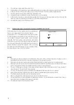
Once this function has been activated, it will give consent for the enabling of the additional heat
source (via a 230V~50Hz signal to the terminals indicated as “Other thermal”) if the outside temper-
ature falls below the value speci
fi
ed in the “T-Other switch on“ parameter or if “Emergen. mode” is
activated.
2.
If you select “Logic 1” or “Logic 2“, the additional heat source must be set so as to produce hot water
with a set-point equal to that selected for the heat pump. This setting must be made manually by the
user, as the heat pump gives consent only (without the possibility to alter the hot water production
set-point on the additional heat source).
3.
If you select “Logic 2”, the system must be designed to supply the terminal side and DHW side with
water at the same temperature (so the system-side terminals must necessarily be
fi
tted with mixer
valves to ensure the hot inlet water is correctly managed).
4.
The supplementary water probe must be installed downstream of the 3-way valve (for more infor-
mation, refer to the installation manual).
5.
The maximum value for the heating set-point is 60°C.
6.
If this function is used, no additional electric heaters can be enabled (Optional E-heater).
7.
If the relative function is activated (paragraph 8.3), the value of these parameters will be stored in the
memory and automatically reset after any possible voltage failure.
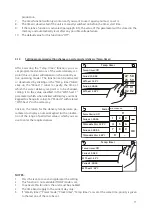
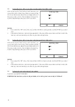
Other thermal
Other thermal: With
T Other switch on: -20°C
Logic: 1
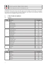
7.8.
Setting an additional heat source (Other thermal)
After accessing the "Other thermal" function, you can
activate or deactivate the substitute heat source and
set the outdoor temperature threshold below which
it will be activated in place of the heat pump, and
choose the logic for managing the substitution. The
available logic items are:
t
Logic 1
: this logic is used to consent to the use of
the substitute heat source to meet system-side
demand only. The 3-way valve will be blocked
on this side, and any requests from the DHW
side will be met using the electric heater of the
water tank (If present).
t
Logic 2:
this logic is used to consent to the use of
the substitute heat source to meet demand from
both the system side and the DHW side. The unit
continues to manage the diverting valve.
t
Logic 3:
this logic disables the heat pump and
activates a 230V signal to the “Other thermal” ter-
minals (for more information, refer to the instal-
lation manual) for activating the additional heat
source (which will work in stand-alone mode,
separate from the HMI unit).
Lastly, press the top right button to save the data en-
tered.
29
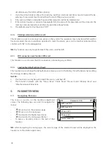
After accessing the “Optional E-heater” function, you can
activate or deactivate any additional electric heater. This
heater may be single-stage or dual-stage (in the case of a
dual-stage model, you can decide whether or not to use
both stages by specifying the number of heaters in the
fi
rst parameter). You can also set the outdoor temperature
threshold below which it will be activated in place of the
heat pump.
WARNING: to ensure the maximum energy
savings, you are advised to use “Logic 1”.
Press the top
right button to save the data entered.
NOTES:
1.
Once this function has been activated, it will give consent for the enabling of the additional electric
heaters (via a 230V~50Hz signal to the terminals indicated as “KM1” and “KM2“; if you use a single
heater, use the “KM1” terminals only) if the outdoor temperature falls below the value speci
fi
ed in the
“T-Eheater“ parameter or if “Emergen. mode” is activated.
2.
The supplementary water probe must be installed downstream of the electric heater (for more infor-
mation, refer to the installation manual).
3.
If this function is used, no additional heat source can be enabled (Other thermal).
4.
Logic 2 is not available.
5.
The electric heater must be installed downstream of the 3-way valve (terminal side of the system).
6.
The DHW request will be met by the electric heater in the water tank (If present).
7.
If the relative function is activated (paragraph 8.3), the value of these parameters will be stored in the
memory and automatically reset after any possible voltage failure.
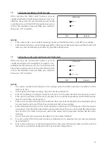
Optional E Heater
Optional E Heater: 1
T Heater: -15°C
Logic 1
7.9.
Setting an additional heater (Optional E-heater)
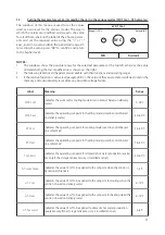
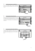
After accessing the “Ambient sensor” function, you
can specify whether or not to enable the remote room
temperature probe (for more information about this
component, refer to the installation manual). Select
the required logic, then press “OK” to con
fi
rm.
Remote sensor
With
Without
OK
Cancel
NOTES:
1.
The “T-remote room“ option in the “Ctrl.state“ function will only be available if the room temperature
sensor is enabled.
2.
If the relative function is activated (paragraph 8.3), the value of these parameters will be stored in the
memory and automatically reset after any possible voltage failure.
7.10.
Setting the installation of the remote room temperature probe (Ambient sensor)
Содержание SHERPA MONOBLOC
Страница 191: ......
Страница 192: ...262617B...


