background image

LCAC

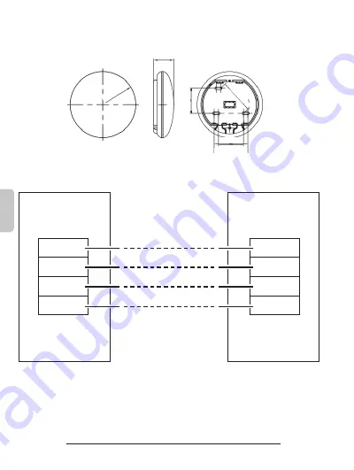
36,8 mm

62 mm

48 mm

48

 mm

62

 mm

Ø

 120

 mm

ES - 4

ESP

AÑOL

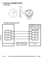
3- MÉTODO DE INSTALACIÓN

Dimensiones

Esquema del principio de conexión

Placa base de la 

unidad interna

Cable blindado de 4 Polos, 

la longitud se decide basa

-

do en la instalación

rojo

negro

amarillo

marrón

rojo

negro

amarillo

marrón

Caja de control Wifi

Inserto de la placa 

principal CN40 o 

CN49 u otras puertas 

indicadas

Содержание B0970

Страница 1: ...ISCO WIFI USER MANUAL EN MANUEL DE L UTILISATEUR BETRIEBSANLEITUNG FR DE MANUAL DE USO ES EL MANUAL DE USO INSTRUKCJA OBS UGI PT PL GEBRUIKERSHANDLEIDING MANUAL DE UTILIZARE NL RO MANUALE D USO IT MAN...

Страница 2: ...agens contidas no presente manual t m uma fun o meramente exemplificativa O aparelho em sua posse pode ser diferente do mostrado Opere de acordo com o seu aparelho Alle afbeeldingen in deze handleidin...

Страница 3: ...di procedere con l installazione leggere con attenzione le avvertenze riportate sul manuale uso del Kit B1020 in allegato 2 PREPARAZIONE ALL INSTALLAZIONE Preparazione prima dell installazione Verifi...

Страница 4: ...Dimensioni Schema del principio di collegamento Scatola di comando Wifi Inserto della scheda madre CN40 o CN49 o altre porte specificate Scheda madre unit interna Cavo schermato a 4 Poli la lunghezza...

Страница 5: ...re una prolunga acquistata separatamente Gruppo 1 cavi di collegamento CN40 o CN49 o altre porte specificate Prolunga Fessure Cavo schermato a 4 Poli Scheda madre Rimuovere la parte superiore del coma...

Страница 6: ...20 Fissaggio della piastra posteriore del comando a muro Per il montaggio a vista fissare la piastra posteriore sul muro con le 3 viti M4 20 e tasselli Inserire lo smart kit all interno del PCB princ...

Страница 7: ...interno del comando a muro utilizzare il sifone e lo stucco per sigillare i connettorideifilidurantel installazionedelcablaggio Durante l installazione lasciare una certa lunghezza del filo di collega...

Страница 8: ...gio durante l installazione 4 DATI TECNICI Tensione in ingresso DC 12V 300mA Temperatura di esercizio 0 C 45 C 32 F 1 13 F Umidit di esercizio 10 85 Massima Potenza Trasmessa 19 BdBm Max Frequenza WIF...

Страница 9: ...nstallation read the warn ings indicated on the attached manual for use of the Kit B1020 with care 2 INSTALLATION ACCESSORY Preparation before installation Please confirm that all the following parts...

Страница 10: ...INSTALLATION METHOD Dimensions Wiring Principle Sketch Indoor unit mainboard 4 Core Shield Cable the length is decided by installation red black yellow brown red black yellow brown Wifi control box I...

Страница 11: ...se use an extension cord pur chased separately The connective wires group 1 Slots 4 core shielding wire Mainboard Remove the upper part of wire controller Insert a flat bladed screwdriver inside the s...

Страница 12: ...Screws M4 20 Fasten the back plate of the wire controller For exposed mounting fasten the back plate on the wall with the 3 screws M4 20 and plugs Insert the smart kit with slightly strength into the...

Страница 13: ..._ Avoidthewaterenterintothewiredremotecontroller use trap and putty to seal the connectors of wires during wiring installation During installation leave a certain length of the con nection wire to eas...

Страница 14: ...ring during installation 4 SPECIFICATION Input voltage DC 12V 300mA Operating temperature 0 C 45 C 32 F 1 13 F Operating humidity 10 85 Maximum Transmitted Power 19 BdBm Max Frequency WIFl 2 4G Antenn...

Страница 15: ...n lire attentivement les mises en garde contenues dans le manuel d utilisation du Kit B1020 joint 2 ACCESSOIRES D INSTALLATION Pr paration avant l installation Veuillez confirmer que toutes les pi ces...

Страница 16: ...N Dimensions Sch ma du principe de c blage Carte m re de l unit int rieure C ble blind 4 conduc teurs la longueur est d termin e par l installation rouge noir jaune marron rouge noir jaune marron Bo t...

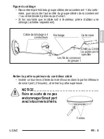
Страница 17: ...une rallonge achet e s par ment Les fils de connexion du groupe 1 Fentes C ble de blindage 4 conducteurs Carte m re Retirer la partie sup rieure du contr leur c bl Ins rer un tournevis fente dans les...

Страница 18: ...re Vis M4 20 Fixer la plaque arri re du contr leur c bl Pour un montage apparent fixez la plaque arri re au mur avec 3 vis M4 20 et les chevilles Ins rer le smart kit l int rieur du PCB principal du p...

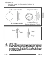
Страница 19: ..._ _ _ _ _ _ _ _ _ _ _ _ Afind viterquedel eaun entredanslat l commande c bl e utilisezunetrappeetdumasticpourscellerles connecteursdesfilspendantl installationduc blage FaireensortedenepasendommagerSm...

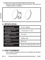
Страница 20: ...installation 4 SP CIFICATION Tension d entr e DC 12V 300mA Temp rature de fonc tionnement 0 C 45 C 32 F 1 13 F Humidit de fonction nement 10 85 Puissance maximum transmise 19 BdBm Max Fr quence WIFl 2...

Страница 21: ...der Installation dieAnweisungen in der Gebrauchsanweisung des Bausatzes B1020 in der Anlage sorgf ltig lesen 2 INSTALLATIONSZUBEH R Vorbereitungen vor der Installation Bitte berpr fen dass alle nachfo...

Страница 22: ...Abmessungen Skizze des Verkabelungsverfahrens Hauptplatine Innen raumger t 4 adriges abgeschirmtes Kabel die L nge wird durch die Installation bestimmt rot schwarz gelb braun rot schwarz gelb braun WL...

Страница 23: ...gerung separat zu erwerben verwenden Den oberen Teil des kabelgebundenen Reglers abnehmen EinenSchlitzschraubenzieherindasInnerederSchlitzeimunterenTeil des Smart Ports 2 Schlitze einf hren und das ob...

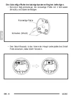
Страница 24: ...denen Reglers befestigen Bei einer Aufputzmontage die r ckseitige Platte mit 3 Schrauben M4x20 und D beln befestigen Den Smart Bausatz in das Innere der Haupt Leiterplatte des Smart Ports einsetzen da...

Страница 25: ...rden dass Wasser in den kabelgebundenenReglereindringt einenVerschluss undKittverwenden umbeiderInstallationdieKabel anschl sse zu versiegeln Darauf achten den Smart PortnichtmitdemSchraubenzieherzube...

Страница 26: ...ht einklemmen 4 SPEZIFIKATIONEN Eingangsspannung DC 12V 300mA Betriebstemperatur 0 C 45 C 32 F 1 13 F Betriebsfeuchtigkeit 10 85 H chste bertragene Leistung 19 BdBm Max Frequenz WLAN 2 4G Antennentyp...

Страница 27: ...eder con la instalaci n lea con cui dado las advertencias indicadas en el manual para el uso del Kit B1020 en anexo 2 PREPARACI N A LA INSTALACI N Preparaci n antes de la instalaci n Verifique que tod...

Страница 28: ...iones Esquema del principio de conexi n Placa base de la unidad interna Cable blindado de 4 Polos la longitud se decide basa do en la instalaci n rojo negro amarillo marr n rojo negro amarillo marr n...

Страница 29: ...able utilice un alargador adquirida separa damente Grupo 1 cables de conexi n Ranuras Cable blindado de 4 Polos Placa base Remueva la parte superior del mando de muro Inserte un destornillador de hoja...

Страница 30: ...Tornillos M4 20 Fijaci n de la placa trasera del mando de muro Para el montaje expuesto fije la placa trasera en el muro con los 3 tornillos M4 20 y tarugos InserteelsmartkitdentrodelPCBprincipaldela...

Страница 31: ...dentro del mando de muro utilice el sif n y la masilla para sellar los conectores de los hilos durante la instalaci n del cableado Durantelainstalaci n dejeunadeterminadalongitud del hilo de conexi n...

Страница 32: ...nte la instalaci n 4 DATOS T CNICOS Voltaje de entrada DC 12V 300mA Temperatura de funcio namiento 0 C 45 C 32 F 1 13 F Humedad de ejercicio 10 85 Potencia M xima Transmitida 19 BdBm Max Frecuencia WI...

Страница 33: ...instala o leia atentamente os avisos no manual de opera o do Kit B1020 em anexo 2 INSTALA O DOS ACESS RIOS Prepara o antes da instala o Por favor confirme que todas as seguintes pe as foram fornecida...

Страница 34: ...ns es Esbo o princ pio de cablagem Placa principal da unidade interior Cabo protetor de 4 n cleos o comprimento decidido pela instala o vermelho preto amarelo castanho vermelho preto amarelo castanho...

Страница 35: ...cabodeextens o adquirido separadamente Remova a parte superior do controlador com fios Insira uma chave de fendas nas ranhuras na parte inferior da porta inteligente 2 ranhuras e remova a parte superi...

Страница 36: ...seira do controlador com fios Para montagem exposta aperte a placa traseira na parede com os 3 parafusos M4x20 e buchas Insira o kit inteligente no PCB principal da porta inteligente for ando ligeiram...

Страница 37: ...oto com fio use trava e massa para vedar os conectores dos fios durante a instala o da cablagem Durante a instala o deixe um certo comprimento do fio de conex o para facilitar as opera es de manuten o...

Страница 38: ...cablagem durante a instala o 4 ESPECIFICA ES Tens o de entrada DC 12V 300mA Temperatura de exer c cio 0 C 45 C 32 F 1 13 F Humidade de funciona mento 10 85 M xima pot ncia trans mitida 19 BdBm M x Fre...

Страница 39: ...de handleiding voor het gebruik van de Kit B1020 staan alvorens tot installatie over te gaan 2 BIJKOMENDE OPMERKING OVER DE INSTALLATIE Voorbereiding van de installatie Controleer of alle volgende ond...

Страница 40: ...ODE Afmetingen Tekening bedradingsprincipe Moederbord binne nunit Afgeschermde Kabel 4 Kernen de lengte wordt bepaald bij installatie rood zwart geel bruin rood zwart geel bruin Wifi bedieningskastje...

Страница 41: ...wordt verzocht een apart gekocht verlengsnoer te gebruiken De bovenkant van de bedrade bediening verwijderen Steek een sleufschroevendraaier in de openingen in het onderste deel van de smart port 2 o...

Страница 42: ...de bedrade bediening bevestigen Zet de achterplaat voor een zichtbare muurmontage vast op de muur met de 3 schroeven M4 20 en pluggen Plaats de smart kit in de hoofd PCB van de smart port door licht...

Страница 43: ...een insluiting en een dichtingsmiddel omdeconnectorenvandedradenteverzegelentijdens deinstallatievandedraden Laattijdensdeinstallatie eenbepaaldelengtevandeaansluitdraadoveromhet onderhoud van de sma...

Страница 44: ...aad hierbij bekneld raakt 4 SPECIFICATIE Ingangsspanning DC 12V 300mA Bedrijfstemperatuur 0 C 45 C 32 F 1 13 F Bedrijfsvochtigheid 10 85 Uitgezonden Maximum vermogen 19 BdBm Max Frequentie WIFl 2 4G T...

Страница 45: ...LCAC EL 3 1 _ _ _ _ _ _ _ _ _ _ _ _ _ _ _ _ _ _ _ _ _ _ KitB1020 2 1 Smart port 1 2 Kit B1020 1 3 3 M4X20 4 3 5 Kit B1020 1 6 1 1 5 7 1 1 1...

Страница 46: ...LCAC 36 8 mm 62 mm 48 mm 48 mm 6 2 m m 120 mm EL 4 3 Wifi CN40 CN49 4...

Страница 47: ...LCAC EL 5 1 1 4 smart smart 2 _ _ _ _ _ _ _ _ _ _ _ _ _ _ _ _ _ _ _ _ _ _ _ _ Smart 1 CN40 CN49 4...

Страница 48: ...LCAC EL 6 3 M4 20 smart PCB smart M4 20...

Страница 49: ...LCAC EL 7 _ _ _ _ _ _ _ _ _ _ _ _ _ _ _ _ _ _ _ _ _ _ _ _ Smart P20mm...

Страница 50: ...LCAC EL 8 Smart 4 DC 12V 300mA 0 C 45 C 32 F 1 13 F 10 85 19 BdBm Max WIFl 2 4G 5 1020...

Страница 51: ...wody Przed przyst pieniem do instalacji przeczyta uwa nie ostrze enia zawarte w za czonej instrukcji obs ugi Zestawu B1020 2 PRZYGOTOWANIE DO INSTALACJI Przygotowania przed instalacj Sprawdzi czy wsz...

Страница 52: ...ymiary G wny schemat po czeniowy Skrzynka sterownicza Wifi Wk ad p yty g wnej CN40 lub CN49 lub inne wskazane porty G wna p yta jednostki wewn trznej Kabel z os on 4 biegu nowy d ugo zostanie okre lon...

Страница 53: ...siprzed u y kabel prosimyu y przed u acz zakupiony osobno ci gn g rn cz p yty sterowniczej na ciennej W o y rubokr t w szczelin w dolnej cz ci inteligentnego portu 2 szczelina i ci gn g rn cz ZANOTUJ...

Страница 54: ...lnej p yty sterowniczej na cianie Dla widocznego monta u zamocowa tyln p yt na cianie przy pomocy 3 rub M4 20 i ko k w W o y inteligentny zestaw do wn trza g wnego PCB inteligentnego portu lekko docis...

Страница 55: ...trza sterowania na ciennego u y syfonuigipsuwceluzapiecz towa niaz czyprzewod wpodczasinstalacjiokablowania Podczas instalacji pozostawi pewn d ugo prze wodu pod czeniowego dla u atwienia czynno ci ko...

Страница 56: ...instalacji 4 DANE TECHNICZNE Napi cie na wej ciu DC 12V 300mA Temperatura pracy 0 C 45 C 32 F 1 13 F Wilgotno robocza 10 85 Maksymalna przekazy wana moc 19 BdBm Max Cz stotliwo WIFl 2 4G Typ Anteny An...

Страница 57: ...epe instalarea citi i cu aten ie instruc iunile con inute n manualul de utilizare a Kit ului B1020 anexat 2 PREG TIRE PENTRU INSTALARE Preg tire nainte de instalare Verifica i dac sunt prezente toate...

Страница 58: ...INSTALARE Dimensiuni Schema de conectare Cutie de comand Wi Fi Inser ie plac de baz CN40 sau CN49 sau alte porturi specificate Plac de baz unitate intern Cablu ecranat cu 4 fire lungimea se decide n f...

Страница 59: ...utiliza i un cablu prelungitor achizionat separat Scoate i partea superioar a comenzii de perete Introduce i o urubelni dreapt n fantele din partea inferioar a portului smart 2 fante i ndep rta i par...

Страница 60: ...terioare a comenzii de perete Pentru montaj aparent fixa i placa posterioar pe perete cu ajutorul celor 3 uruburi M4 20 i dibluri Introduce i kit ul smart n PCB ul principal al portului smart for nd u...

Страница 61: ...omandadeperete folosi i sifonul i stucul pentru a etan a papucii firelor n timpul instal rii cablajului n timpul instal rii l sa i o anumit lungime a firului de conexiune pentru a facilita opera iunil...

Страница 62: ...timpul instal rii 4 DATE TEHNICE Tensiune de intrare DC 12V 300mA Temperatur de func i onare 0 C 45 C 32 F 1 13 F Umiditate de func ionare 10 85 Putere maxim trans mis 19 BdBm Max Frecven WIFl 2 4G Ti...

Страница 63: ......

Страница 64: ...265763B...

Отзывы: