16
IMTP 2.2 - ITTP 2.2/4/5.5/7.5
ENG
6.4 Alarms
Alarm
Number
Alarm Type
Description
1
Current Peak
Immediately stop probably caused by short-circuit
Automatic re-start; final stop after 10 consecutive events
2
Over-Voltage
Normally caused by over voltage pick supply. Automatic re-start; final
stop after 10 consecutive events
3
Inverter Temperature
Over temperature IGBT protection (90¡C)
Automatic re-start; final stop after 10 consecutive events
4
I
2
T exceeded
Motor thermal protection related to nominal current set, for motor
insulations saving at high temperatures. Automatic re-start; final stop after
10 consecutive events
5
Dry working
Null input flow or air presence;
Automatic re-start; final stop after 5 consecutive events
6
Pressure sensor problem
Pressure sensor output problem
Automatic re-start; final stop after 10 consecutive events
7
Minimum flow
The pump stop for minimum flow limit achievement.
It’s a normal
working condition of the system
(no demand
of water on the delivery) even thug is on the alarm list,
Automatic re-start; no limits
8
Enable OFF
Open contact between EN e C (figure 5 e 8): stop the motor; the motor
restart when the contact will close again
9
Over-temperature
microprocessor
The microprocessor temperature exceed a limit value, then the system
must stop until the temperature return low.
Automatic re-start; final stop after 10 consecutive events
10
Over-current
High current combined with a low limited velocity. Automatic re-start; final
stop after 10 consecutive events
11
Braking current peak
Current peak on the braking resistors; Automatic re-start; final stop after
10 consecutive events
12
Error current reading
Mistake on the current reading; the motor stop to prevent possible
damage caused by the faulty current control.
Automatic re-start; final stop after 10 consecutive events
13
Input Voltage under limit
Input voltage under the minimum working limit.
Automatic re-start; final stop after 10 consecutive events
14
Unbalanced current
Unbalanced currents on the three phases (>15% on RMS value)
Automatic re-start; final stop after 10 consecutive events
15
INPUT-OUTPUT cable reverse
Connection mistake: Voltage supply connected on the output and Motor
cable connected on the entrance: reverse in order to enable the motor
Table 9: Alarms
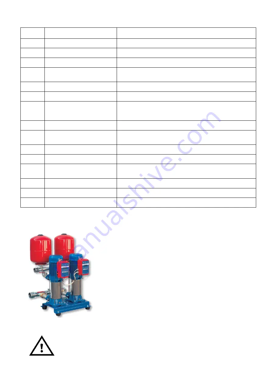
6.5 Group Functioning - data transmission via serial bus RS485
Pumps controlled by inverters communicating with RS485 in control logic
MASTER Ð SLAVE type:
1.
Connecting all Inverters with a bipolar signal cable for RS485,
respecting the polarity A and B (J10 clamp on Fig. 5 and J2 on fig.8);
2.
Set the MASTER inverter: Advanced Functions Ð Group Functioning -
MasterSlave; Code = 0; N¡ Pumps (³2);
3.
Set on the remaining SLAVES Inverters (maximum 8): Advanced
Functions Ð Group Functioning - MasterSlave; Code (³1) ; N¡ Pumps (³2).
IMPORTANT: The Master-Slave group setting may be done after the self-
regulation check, as described on 6.1. Use one sensor for every Inverter to
guarantee the redundancy and the group functioning continuity in case of
damage of one of the Motors/Sensors/Inverters; when a sensor have a
problem the Master Inverter read the output of a sensor connected to one
other slave Inverter. For this functioning is important the good state of charge of the battery of Master Inverter,
to maintain the date.
During group functioning in case of break voltage or fault to the Master Inverter or to the serial
bus cable, the others Inverters continuous functioning in single mode, reading their pressure
sensors. Although there is not inefficiency of the complete system, restore the damaged
cable/sensor/inverter in order to guarantee the perfect pressure control and the perfect
alternation of the pumps and its duration.


