Construction Manual
www.oldschoolmodels.com
Page 9
British
Sunday Fighter
Bristol Spadport
Step 45 - Bottom Wing Assembly (R2 cutout)
Just as you did for the top wing halves, it’s time to mark and
cutout the slots in R2 to accept the dihedral braces. These are be
rectangles and is positioned between the upper and lower spars,
as well as the front and rear sheer webs.
Use a rotary tool for the main portion, then a sharp hobby knife
for the corners. Take care not to damage the balsa sheer webs or
weaken the spars.
Step 46 - Wing Assembly (sanding)
Sand the tip and root ribs of all four wing halves to remove any
extra spar and sheeting material. Make sure they have smooth,
flat surfaces. Attach TR1 and TIP to the tip ribs, as you did on the
upper wing.
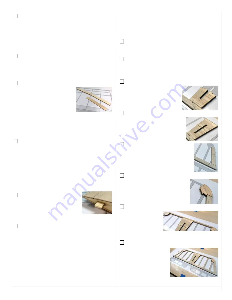
Step 47 - Wing Assembly (DH1/DH2)
Locate two DH1’s from LP1 and four
DH2’s from BP9. These pieces are
laminated together with a thin layer
of epoxy to form two identical wing
dihedral braces.
Two DH2’s are glued to each side of each
DH1 to form thicker pieces.
Note that there is an etched circle in each DH2 that designates the
angled cut. Align these properly so it matches the angle of DH1.
To insure the pieces stay perfectly aligned, clamp or weigh down
both assemblies until the glue fully cures.
Step 48 - Wing Assembly (join wing halves)
Now take one of the assembled dihedral braces and test fit into
the wing slots of the top wing halves. You will probably have to do
a bit of sanding on the brace to allow it to easily fit into each slot.
Don’t take off too much, too fast. Carefully sand as necessary to
make sure everything fits properly and the root ribs in each wing
half are touching along their entire length when assembled into a
single wing. Take your time and get a good fit that doesn’t require
a lot of force.
Once you’re happy with the top wing’s fit, do the same with the
bottom wing halves and the remaining dihedral brace assembly.
Step 49 - Wing Assembly (PIN)
Locate both PIN’s from LP3. These are anti-
rotation pins and are used to help align the
rear portion of the wings.
Glue one PIN halfway in the upper port wing
half and the other halfway in the lower port wing half.
Step 50 - Wing Assembly (join wing halves)
Test fit the wing halves together one last time and sand as necessary
for a good fit.
After test fitting, join the top wing halves permanently with a bit
more 30 minute epoxy. Remove the dihedral brace and apply the
epoxy into the pockets in each wing half and also coat the faces of
each root rib.
Slide all the dihedral brace into one of the wing halves, then slide
remaining wing half in place. Using a couple of clamps (or tape),
hold wing halves firmly together. Wipe off any excess epoxy and
remove the clamps only after the epoxy has fully cured.
Remember, any twist in the alignment of the panels cannot be
fixed after the epoxy cures and will lead to a poor flying model.
Set the top wing aside and then do the same to assemble the
lower wing.
This completes assembly of the Sunday Fighter wings.
Now it’s time to start construction of the tail surfaces.
Prepare your work area
Now tape the elevator/stab plan and a fresh piece of waxed paper
on your building board.
Step 51 - Horizontal Stab Assembly (trailing edge)
Locate the 1/4” x 1/2” balsa strip and cut two pieces to form the
trailing edge of the horizontal stab as shown on the plans. Pin these
two pieces in position, making sure they are in-line with each other.
Step 52 - Horizontal Stab Assembly (S2)
Locate both S2’s from BP1. These are
glued in place in the center of the stab,
one on top of the other, resting against
the trailing edge pieces. Glue these in
place.
Step 53 - Horizontal Stab Assembly (S1)
Locate both S1’s from BP1. These are glued
in place in the center of the stab, one on top
of the other, resting against the S2 pieces
you just installed. Glue these in place.
Step 54 - Horizontal Stab Assembly (tips)
Cut both outer tips of the stab from the 1/4” x
1/2” balsa strip you used earlier - one for the left
and one for the right. Glue these in place and pin
them to hold them while the glue cures.
Step 55 - Horizontal Stab Assembly (corners)
Cut four S3’s from BP1. Two are used to create
the front corner on each side. Glue one on
top of the other, then to the tip piece you just
installed.
Pay close attention to their orientation.
Step 56 - Horizontal Stab Assembly (leading edge)
Using 1/4” square balsa,
measure, cut and glue in
the leading edge of the
stab. Check your scrap
pile to see if you have the
proper length first, but if not, use an uncut length.
Step 57 - Horizontal Stab Assembly (bracing)
Using 1/4” square balsa,
measure, cut and glue in center
bracing of the stab. Check your
scrap pile using any possible
shorter lengths first before
reverting to longer, uncut
lengths.


