background image

PEC Flaw Detector PE4332   Operation Manual 


+7(812) 385-54-28 

[email protected] 


34


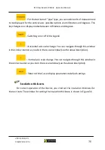
 – For the test item of "pipe" type, you can select units of measurement 

to be displayed for  the vertical axis; possible options are millimeters and degrees. This 
key changes over display modes between millimeters and degrees. 

 – Switching on or off of the legend. 

 – Horizontal axis scale change. You can navigate through this window 

in the similar manner as you do in the A-scan window (see the above description). 

 – Vertical axis scale change. You can navigate through this window in 

the similar manner as you do in the A-scan window (see the above description). 

 – Return of the C-scan display parameters to default settings. 

Insulation thickness


For correct operation of the Device, you shall set the insulation thickness for 

the test item. The window for setting the insulation thickness is shown in Figure 34. 

Содержание PE4332

Страница 1: ...7 812 385 54 28 info oktanta ndt ru PEC Flaw Detector PE4332 Operation Manual Saint Petersburg 2021...

Страница 2: ...continuation menu 13 Calibration 15 Grid 16 Test item parameters 24 Diagrams 31 Insulation thickness 34 Thresholds 35 Averaging 37 Main menu 38 DEVICE OPERATION 44 Sensor Selection 44 Thickness Measur...

Страница 3: ...aw Detector PE4332 PEC Flaw Detector PE4332 is designed to detect corrosion under insulation without removal of the latter The Device is used to inspect such items as Insulated pipelines including pip...

Страница 4: ...thick paint or epoxy coating Figure 5 Ship hull The Device allows testing such items without preliminary surface preparation or insulation removal The insulation can be represented with any non conduc...

Страница 5: ...displays the demagnetization process is A scan shown in Figure 6 Figure 6 A scan appearance The greater is the metal thickness under the sensor the longer is the demagnetization process on A scan and...

Страница 6: ...10 Thickness range for insulation coating depends on insulation thickness and sensor see Sensor Selection 0 to 300 mm Minimum diameter of tested pipes 50 mm Temperature of test item metal 100To to 60...

Страница 7: ...4332 You can see the Device itself and the sensor connected with the Device using the cable Figure 7 PEC Flaw Detector PE4332 appearance Device The Device is incorporated into a plastic impact resista...

Страница 8: ...connectors 6 recharger connector 7 holder for Device installation on flat surfaces For Device display appearance see Figure 9 Figure 9 Device display There are five main screen panels They are numbere...

Страница 9: ...e Panel 4 This panel displays C scan of the Device Panel 5 This panel displays icons with functional keys The Device has the keyboard The functional keys of the keyboard are described in Table 1 Table...

Страница 10: ...creen for a point with minimum metal thickness detected Multi functional keys Various functions specified by the icons Sensor Figure 10 shows the appearance of the sensor The sensor is made of impact...

Страница 11: ...or of a switched on encoder Indicator of activated scan mode Metal thickness Insulation thickness Coordinates of the current position on C scan The Device sensor has its own keyboard The keyboard keys...

Страница 12: ...and off of the encoder WARNING During operation of the PEC Flaw Detector PE4332 the sensor generates a large pulsed magnet field Be careful when using the sensor as the field can magnetize such sharp...

Страница 13: ...to C scan grid edition menu Access to test item parameter change menu Access to A scan and C scan navigation menu Access to insulation thickness setting menu Access to rejection requirements rejectio...

Страница 14: ...t the appropriate menu item press on the key These menu items allow to start new scanning stop scanning as well as to continue the stopped scanning New scan Figure 14 shows Start new scanning window I...

Страница 15: ...anned only part of the test item and then he she can return to the test item few days later and continue scanning To do this the user shall open the archive with non completed scan see Section Main me...

Страница 16: ...hange to change value from 0 to 9 for each digit position selected using the keys If necessary you can set the digit position value by pressing on the keys Grid When you use the scan mode you shall pu...

Страница 17: ...cale 123 ABC The first option is used when the grid has fixed linear dimensions the second one is used when linear dimensions are not important To change the scale use the keys or the keys with the ic...

Страница 18: ...as through the Horizontal spacing menu item Horizontal scanning site length This parameter is used to set the horizontal size of the scanning site This parameter can vary from 1 to 50 m Navigation thr...

Страница 19: ...is end the Device has the keyboard mode see Figure 12 To navigate through the keyboard use the keys The selected character is entered when the key is pressed on To complete entry of the name and to ex...

Страница 20: ...g information and exit from the keyboard mode Quick change over between the keys similarly marked on the keyboard Bck Erasion of one character Clr or Undo Complete clearing of the entry field or cance...

Страница 21: ...s window to delete the unnecessary grid To this end select its name from the list using the keys and press on the key under the icon To quit the menu press on the key Set grid position For correct dis...

Страница 22: ...recommend to use our self adhesive grids An example of such grid located on the pipe is shown in Figure 21 Figure 21 Self adhesive grid on the pipe Use of this grid will save time for its drawing To...

Страница 23: ...22 To change over between the number registers use the keys under the icons or the keys The keys under the icons and the icons are used to change value of the selected digit position Figure 22 Quick e...

Страница 24: ...Grid application To confirm the selected operation use the key under the icon WARNING You can get access to Grid menu through the Device main menu key Test item parameters To operate the Device you s...

Страница 25: ...test item shape use the keys or the keys under the icons There are two options pipe and sheet Casing material This menu item is used to select the material of the protective casing To select the mate...

Страница 26: ...each position using the keys or the keys under the icons Pipe wall thickness You shall set the nominal thickness of the pipe wall The pipe wall thickness is entered in the same manner as above descri...

Страница 27: ...when the user subsequently fills C scan with measurements in the grid nodes To make the adjustment set the insulation thickness in 4 points at the scan area beginning and in 4 points at the scan area...

Страница 28: ...etween the digit positions use the keys or the keys under the icons Enter the insulation thickness in the given point using the keys under the icons or the keys Press on the key after entry Measure th...

Страница 29: ...ses in points 3 8 in the same manner as you did in point 2 Manual mode In this mode you can manually enter the insulation thickness for each of 8 points To this end you shall enter insulation thicknes...

Страница 30: ...a ndt ru 30 Figure 29 Insulated pipe diameter entry To enter the pipe diameter use the keys under the icons see Figure 29 or the keys For quick entry you can use the key under the icon In this case th...

Страница 31: ...changes press on the key WARNING You can get access to test item parameters menu through the Device main menu key Diagrams This item is used to change the scale on the Device diagrams The Device has t...

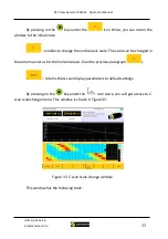
Страница 32: ...the A scan window to the mode of changing the maximum value along this axis This window is shown in Figure 32 Figure 32 Change of A scan size along the horizontal axis You can change the maximum value...

Страница 33: ...hange the vertical axis scale The scale can be changed in the same manner as for the horizontal axis See the previous paragraph returns the A scan display parameters to default settings By pressing on...

Страница 34: ...Horizontal axis scale change You can navigate through this window in the similar manner as you do in the A scan window see the above description Vertical axis scale change You can navigate through th...

Страница 35: ...he keys or the keys under the icons After entry of the insulation thickness press on the key Thresholds The PEC Flaw Detector PE4332 has the scan mode using which you can fill C scan with thickness me...

Страница 36: ...lds are displayed on C scan in color according to the legend shown in Figure 35 Each threshold has both the absolute value in mm and the relative value of the thickness in percents relative to the nom...

Страница 37: ...umber selection window is shown in Figure 36 Figure 36 Averaging number change Select averaging number from the list using the and keys After selection of the required averaging number press on the ke...

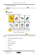
Страница 38: ...main menu key in the Settings tab Main menu Figure 37 shows the Device main menu Figure 37 Device main menu You can get access to this menu by pressing on the key when you are in the Device main windo...

Страница 39: ...menu appearance see Figure 38 Figure 38 Window for selection the archive for opening To open the required archive select it from the list of available files using the keys and press on the key or the...

Страница 40: ...o USB A connector and select the Device menu the USB drive operation menu item In this case the window shown in Figure 39 will appear on the Device screen Figure 39 Window for data copying to the USB...

Страница 41: ...on the GPS coordinates To switch on or off the GPS receiver use the keys or the keys under the icons Averaging You can change the averaging number see Section DEVICE MENU To change the averaging numb...

Страница 42: ...use the keys The selected character is entered when the key is pressed on To complete entry of the name and to exit from this window press on the key under the icon see Figure 41 Table 5 shows the ico...

Страница 43: ...board mode Quick change over between the keys similarly marked on the keyboard Bck Erasion of one character Clr or Undo Complete clearing of the entry field or cancellation of entry field clearing DAT...

Страница 44: ...save the thicknesses measured in the grid nodes in the Device memory When a large data array is not required and it is enough to measure only a few test points then you can use the simple mode of thi...

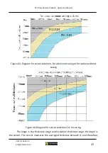
Страница 45: ...Diagram for sensor selection for aluminum casing or for option without casing Figure 44 Diagram for sensor selection for tin casing The larger is the thickness range and insulation thickness range th...

Страница 46: ...ing Then according to Figure 44 you shall use sensor PEC433203 and other transducer will not work in this case Average thickness measurement area The Device measures the average thickness in a certain...

Страница 47: ...mm 230mm X 95mm 240mm X 100mm 280mm X 110mm 310mm 120 mm 340mm X 130mm 380mm X 140mm 410mm X 150mm PEC433203 315mm X 135mm 330mm X 140mm 350mm X 145mm 380mm X 155 415mm X 165mm 450mm X 175mm 480mm X 1...

Страница 48: ...ach of the above items Thickness Measurement The PE4332 measures thicknesses by analyzing the metal demagnetization under the sensor The demagnetization process is always displayed on A scan An exampl...

Страница 49: ...hickness and the material of the insulation casing If such situation arises then it is necessary to enter the correct parameters It is also necessary to ensure that before crossing the threshold the d...

Страница 50: ...You shall also enter data in the menu Test item parameters particularly nominal thickness of the test item material of the insulation casing and thickness of the insulation casing Any thickness measu...

Страница 51: ...n the test item to perform measurements in the grid nodes We produce the special self adhesive grid which can be attached to the test item The example of such grid is shown in Figure 50 Figure 50 Exam...

Страница 52: ...ation thickness Open the menu Grid In this menu set all grid parameters such as vertical size horizontal size vertical grid spacing horizontal grid spacing Or you can loaf the grid data from the pre s...

Страница 53: ...ing through the menu Scanning Start Stop Continuation Menu In this case the main window of the Device will appear as shown in Figure 52 Figure 52 Main window of the Device in scan mode In this case th...

Страница 54: ...e sensor are displayed on the sensor screen You shall install the sensor in the grid node with coordinate 0 0 The Device sensors have the keyboard with a cross you shall install the sensor so that the...

Страница 55: ...move the sensor to the next grid node for example point 100 0 and press on the key of the sensor keyboard The example of sensor location at the second step of scanning is shown in Figure 55 Figure 55...

Страница 56: ...nsor position indicator on C scan to the next line beginning This position is shown in Figure 57 Figure 57 Sensor indicator position at the second line beginning You shall carry the sensor to the begi...

Страница 57: ...Figure 59 Figure 59 Example of C scan During filling C scan monitor the signal waveform on A scan see Thickness Measurement Encoder You can use the encoder in the scan mode To this end press on the k...

Страница 58: ...each archive will be saved in an individual folder with file in CSV format which can be used Data transfer using PC connection You can connect the PEC Flaw Detector PE4332 to the PC using a USB B USB...

Страница 59: ...without the screwdriver Remove the battery by the D rings Install the new battery Tighten the screws WARNING The battery of the PEC Flaw Detector PE4332 is a 12 V 18Ah lithium ion battery Do not disas...

Страница 60: ...e the encoder from the scope of supply Fix the encoder on the sensor housing using screws Switch on the Device The encoder layout on the sensor is shown in Figure 61 Figure 61 Encoder layout on the se...

Страница 61: ...damages of the case and Device The Device battery will discharge during long term storage Long term discharge state of the battery can reduce its capacity So we recommend to perform regular check at...

Страница 62: ...1 The Device is used for purposes other than those specified in this operation manual 2 The equipment operation storage and transportation conditions and requirements specified in this operation manua...

Страница 63: ...PEC Flaw Detector PE4332 Operation Manual 7 812 385 54 28 info oktanta ndt ru 63 INFORMATION ABOUT REPAIR Date of Application Fault Type Repair Completed Not Completed Date Signature Stamp...

Отзывы: