OKM AH6 Скачать руководство пользователя страница 125

Chapter  6  Robot  Operation 

Document Version V1.2.0 (01/06/2023) 


99 


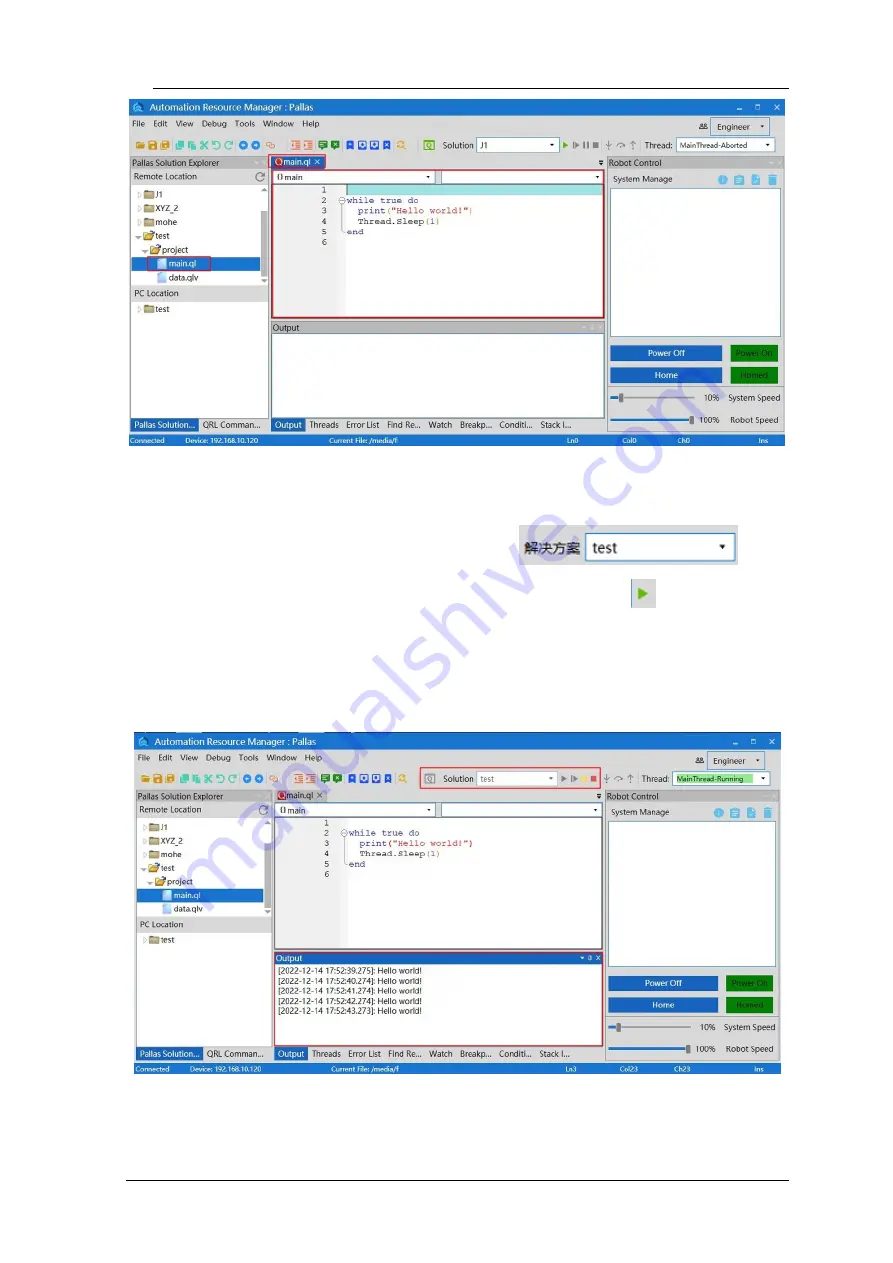
Figure 6-30 "main.ql " interface 

Run the "test" solution; Select "test" in 

  at the 

top of the ARM debugging interface and click the button 

  to run it. At this 

point, the program will output "Hello world!" below in a circular way, as shown 

in Figure 6-31. 


Figure 6-31 Run the solution 

Содержание AH6

Страница 1: ......

Страница 2: ...User Manual AH6 Robot AH6 0500 0204 2000 AH6 0500 0204 3000 AH6 0600 0204 2000 AH6 0600 0204 3000 AH6 0700 0204 2000 AH6 0700 0204 3000 QKM Technology Dongguan Co Ltd Version V1 2 0 Date 01 06 2023...

Страница 3: ...ides detailed information on product features main components installation guide system debugging and technical specifications of AH6 Robot so that users can fully understand and properly use the robo...

Страница 4: ...a dangerous situation would occur and cause deaths or serious injuries if it is not avoided It indicates that a potentially dangerous situation would occur and cause personal injuries or equipment dam...

Страница 5: ...related parts Trademark is the trademark of QKM Technology Dongguan Co Ltd QKM Technology has the ownership of this trademark Disclaimer Quotient Kinematics Machine has no obligation or responsibility...

Страница 6: ...chnology Dongguan Co Ltd Tower A Building 17 Headquarters 1 No 4 Xinzhu Road Songshan Lake High tech Industrial Development Zone Dongguan Guangdong China Tel 86 0769 27231381 Fax 86 0769 27231381 8053...

Страница 7: ...document Version Issue Date Revision Content V1 0 0 04 17 2020 The first version V1 1 0 8 26 2020 1 Delete the foreword and back cover address of East China branch 2 Delete Section 5 7 Removal of fix...

Страница 8: ...are added 5 3 Instruction input case description output failure warning and jog operation mode switching description are added 5 4 Modify the tool function description of servo power on interface macr...

Страница 9: ...ds notes on the use of 24V DC output power supply of I O interface with do and notes that 24V DC output power supply cannot be connected to external equipment 3 A detailed description of I O free allo...

Страница 10: ...erface picture and operation steps of the new version of ARM in Section 6 3 4 Modify Section 6 4 Macro Command Debugger Function Introduction and Operation Procedures 5 Added Section 6 5 QRL Mode Desc...

Страница 11: ...Version History Document Version V1 2 0 01 06 2023 IX Added 6 10 Robot power off method 1 and method 2 operation steps and added method 3...

Страница 12: ...f Figures XVI List of Table XXII Chapter 1 Safety Precautions 1 Precautions for general safety 1 1 2 Precautions for safe operation 4 1 3 Safety signs 5 Product Overview 7 2 1 Introduction 7 2 2 Model...

Страница 13: ...Cable 14 3 2 Trajectory 14 3 3 Work space 15 Vertical Work Space 15 Horizontal Work Space 19 3 4 Robot coordinate system 20 3 5 Specification and dimension 21 Overall dimension 21 Base dimensions 25...

Страница 14: ...face panel 34 4 2 Indicator description 35 Main power indicator 35 System indicator Mechanical arm 2 36 4 3 Definition of interface pins 36 Power interface POWER 36 Auxiliary encoder 37 MCP interface...

Страница 15: ...5 4 Installation of external parts 56 Installation of camera optional 57 5 5 Handling of robot 58 5 6 Base installation 60 5 7 Ground protection 61 5 8 Installation of robot cable 61 Communication con...

Страница 16: ...d Debugger 74 6 4 Functions of macro command debugger 77 Macro Command Debugger interface 77 Menu bar 77 Introduction to user defined instruction editing area 79 Establish IP communication 81 Query on...

Страница 17: ...data qlv 100 Saving and downloading program locally 106 6 6 Manual jog teach 108 6 7 Servo power on 111 6 8 Speed adjustment 114 Adjustment of system speed 115 Adjustment of robot speed 116 Speed adj...

Страница 18: ...arm length of 600 mm 16 Figure 3 5 Vertical work space of AH6 Robot with an arm length of 700 mm 17 Figure 3 6 AH6 0500 0204 2000 AH6 0500 0204 3000 19 Figure 3 7 AH6 0600 0204 2000 AH6 0600 0204 300...

Страница 19: ...ce panel 32 Figure 4 3 Schematic diagram of interface panel 33 Figure 4 4 Schematic diagram of interface panel 35 Figure 4 5 Auxiliary encoder 39 Figure 4 6 Wiring diagram of emergency stop device 41...

Страница 20: ...ion of power cable to socket and robot 65 Figure 6 1 Installation package 72 Figure 6 2 Start installation 73 Figure 6 3 Choose installation path 73 Figure 6 4 Successful installation 74 Figure 6 5 AR...

Страница 21: ...Macro manual 88 Figure 6 18 Input instructions 89 Figure 6 19 Input instructions 90 Figure 6 20 Input instructions 91 Figure 6 21 Run instructions 92 Figure 6 22 Add a breakpoint 93 Figure 6 23 Output...

Страница 22: ...6 36 New Location Array 103 Figure 6 37 Location Array information interface 104 Figure 6 38 New LocationJ Array 104 Figure 6 39 LocationJ Array information interface 105 Figure 6 40 New Profile Arra...

Страница 23: ...n V1 2 0 01 06 2023 XXI Figure 6 47 Teach interface 109 Figure 6 48 Power on button interface 114 Figure 6 49 Adjustment of system speed 115 Figure 6 50 Speed adjustment 117 Figure 6 51 Interface of t...

Страница 24: ...length of 700 mm 17 Table 3 4 Dimensions of AH6 Robot with an arm length of 500 Unit mm 22 Table 3 5 Dimensions of AH6 Robot with an arm length of 600 Unit mm 23 Table 3 6 Dimensions of AH6 Robot with...

Страница 25: ...Table 4 10 Definition of Ethernet interface pins 41 Table 4 11 Definition of I O interface pins 43 Table 4 12 Definition of upper control cabinet CS interface pins 48 Table 4 13 Definition of mechanic...

Страница 26: ......

Страница 27: ...l and equipment losses caused by illegal operations Personnel who use AH6 Robot for system design operation and maintenance must be trained by QKM or relevant institutions or have the same professiona...

Страница 28: ...Users should ensure that the robot operates under safety conditions There should be no objects around the robot which may cause damage to it As the robot may be scratched and bumped due to the motion...

Страница 29: ...ty precautions and proper methods of operation and maintenance before operating and maintaining the robot Users should carry out regular inspection and maintenance of the robot according to the manual...

Страница 30: ...accidents Do not enter the work area of the robot after it is powered on to prevent danger Please observe the following safety rules when conducting installation teaching and programming of the robot...

Страница 31: ...nd environmental protection Users should carry out regular inspection and maintenance of the robot according to the manual and related requirements and timely replace damaged parts to ensure safe oper...

Страница 32: ...observe the cautions and contents on the warning signs Table 1 1 Warning signs No Label Remark 1 A triangle sign for warning of high voltage 2 A grounding sign 3 Do not disassemble the robot to preve...

Страница 33: ...M Technology Dongguan Co Ltd hereinafter referred to as QKM It is characterized by AIO design no separate control cabinet and with compact structure greatly overthrowing the layout of traditional indu...

Страница 34: ...AH6 Robot User Manual 8 Document Version V1 2 0 01 06 2023 phone 3C food and other industries Figure 2 1 AH6 Robot AH6 0500 0204 2000 appearance...

Страница 35: ...n Figure 2 2 Model implication Table 2 1 Model preview Model Name Rated Load kg Maximu m Load kg Horizontal Work Space mm Vertical Work Space mm Installatio n Protection Grade Operating Environment AH...

Страница 36: ...AH6 Robot User Manual 10 Document Version V1 2 0 01 06 2023 AH6 0600 0204 2000 600 200 AH6 0600 0204 3000 300 AH6 0700 0204 2000 700 200 AH6 0700 0204 3000 300...

Страница 37: ...sign without separate control cabinet for less space and easy installation By adopting a new generation of distributed architecture control system it is more stable smoother and easier to use Built in...

Страница 38: ...ugated pipe including cables Its appearance and structure are shown in Figure 3 1 Figure 3 1 Composition of AH6 Robot AH6 0500 0204 2000 Upper control cabinet The control cabinet adopts casting moldin...

Страница 39: ...tion location of the base for accurately fixing the robot Mechanical arm 1 Casting design with light weight is used for improving the performance of the robot Mechanical arm 2 Three groups of motors a...

Страница 40: ...ty cables which can ensure smooth signal transmission of the robot 3 2 Trajectory Joint coordinate of robot control system The posture of the robot is represented by rotation angle of each axis The an...

Страница 41: ...5 3 3 Work space Vertical Work Space AH6 0500 0204 2000 AH6 0500 0204 3000 Figure 3 3 Vertical work space of AH6 Robot with an arm length of 500 mm Table 3 1 Vertical work space of AH6 Robot with an a...

Страница 42: ...6 2023 AH6 0600 0204 2000 AH6 0600 0204 3000 Figure 3 4 Vertical work space of AH6 Robot with an arm length of 600 mm Table 3 2 Vertical work space of AH6 Robot with an arm length of 600 mm Model A B...

Страница 43: ...arm length of 700 mm Table 3 3 Vertical work space of AH6 Robot with an arm length of 700 mm Model A B AH6 0700 0204 2000 200 612 AH6 0700 0204 3000 300 712 B indicates the distance between the highes...

Страница 44: ...AH6 Robot User Manual 18 Document Version V1 2 0 01 06 2023 bottom of the spline shaft...

Страница 45: ...pter 3 Components and Functional Description Document Version V1 2 0 01 06 2023 19 Horizontal Work Space Figure 3 6 AH6 0500 0204 2000 AH6 0500 0204 3000 Figure 3 7 AH6 0600 0204 2000 AH6 0600 0204 30...

Страница 46: ...Manual 20 Document Version V1 2 0 01 06 2023 Figure 3 8 AH6 0700 0204 2000 AH6 0700 0204 3000 3 4 Robot coordinate system The and indicating directions of the axes are applicable to the cartesian coo...

Страница 47: ...ter 3 Components and Functional Description Document Version V1 2 0 01 06 2023 21 Figure 3 9 World coordinate system 3 5 Specification and dimension Overall dimension AH6 0500 0204 2000 AH6 0500 0204...

Страница 48: ...6 Robot with an arm length of 500 Unit mm Table 3 4 Dimensions of AH6 Robot with an arm length of 500 Unit mm Model A B C AH6 0500 0204 2000 200 610 1 7 AH6 0500 0204 3000 300 710 98 3 C The positive...

Страница 49: ...sions of AH6 Robot with an arm length of 500 Unit mm AH6 0600 0204 2000 AH6 0600 0204 3000 Figure 3 12 Dimensions of AH6 Robot with an arm length of 600 Unit mm Table 3 5 Dimensions of AH6 Robot with...

Страница 50: ...ive value is above the base datum plane and the negative value is below the base datum plane Figure 3 13 Dimensions of AH6 Robot with an arm length of 600 Unit mm AH6 0700 0204 2000 AH6 0700 0204 3000...

Страница 51: ...00 0204 2000 200 612 3 7 AH6 0700 0204 3000 300 712 96 3 C indicates the distance between the bottom of the spline shaft and the base datum plane its positive value is above the base datum plane and i...

Страница 52: ...AH6 Robot User Manual 26 Document Version V1 2 0 01 06 2023 Terminal flange dimensions Figure 3 17 Installation dimensions of terminal flange Unit mm completely through hole...

Страница 53: ...Model AH6 0500 0204 2000 AH6 0500 0204 3000 AH6 0600 0204 2000 AH6 0600 0204 3000 AH6 0700 0204 2000 AH6 0700 0204 3000 Arm length mm Full arm length 500 600 700 J1 225 325 425 J2 275 275 275 Maximum...

Страница 54: ...ximum load Kg 6 J4 rated moment of inertia kg m2 0 01 J4 maximum moment of inertia kg m2 0 12 Total weight kg 27 28 29 3 7 Environmental parameters Install the robot system in an environment that meet...

Страница 55: ...gas dust or liquid No corrosive gas or substance Free from electromagnetic interference source electrostatic discharge etc in the vicinity Vibration Free from influence by strong impact and vibration...

Страница 56: ...the robot would be affected 3 8 Electrical parameters Table 3 9 Robot electrical parameters Item Parameter Rated voltage 230 V a c 50 60 Hz Rated power 0 9 kW Motor brake voltage 24 V d c I O interfac...

Страница 57: ...roduction to Electrical Interfaces Document Version V1 2 0 01 06 2023 31 Introduction to Electrical Interfaces 4 1 External electrical interface Figure 4 1 External interface panel Mechanical arm 2 in...

Страница 58: ...panel description No Name Description No Name Description 1 CS Customer signal interface Customer Signal 4 Air pipe connecto r Connected to 4 air pipe 2 Indicato r ON green indicates that the robot h...

Страница 59: ...ion to Electrical Interfaces Document Version V1 2 0 01 06 2023 33 3 Brake Brake button 6 Air pipe connecto r Connected to 6 air pipe Upper control cabinet interface panel Figure 4 3 Schematic diagram...

Страница 60: ...to 6 air pipe 5 CS Customer signal interface Customer Signal Air2 Connected to 6 air pipe Air3 Connected to 4 air pipe 2 MCP Emergency stop component interface teach pendant interface 6 I O Digital in...

Страница 61: ...me Description No Name Description 1 AC LED Main power indicator 2 POWER Power interface 3 Groundin g screw hole For grounding 4 2 Indicator description AH6 Robot is equipped with AC LED on the base i...

Страница 62: ...the system indicator is described below Table 4 5 Description of system indicator status Status Description OFF Indicates that the robot is not in the servo state ON green Indicates that the robot has...

Страница 63: ...wire 4 Idle Auxiliary encoder Table 4 7 Definition of auxiliary encoder pins Auxiliary Encoder Axis No Pi n Function Description Axis 1 01 Output 5 V d c 5 V d c output power The 5V pin in the auxili...

Страница 64: ...2023 02 GND Common ground 12 pin female front pinout 03 1A Axis 1 A 04 1B Axis 1 B 05 1Z Axis 1 Z 06 F G Shielded cable Axis 2 07 Output 5 V d c 5 V d c output power 08 GND Common ground 09 2A Axis 2...

Страница 65: ...ument Version V1 2 0 01 06 2023 39 Figure 4 5 Auxiliary encoder MCP interface MCP E stop Table 4 8 MCP Definition of MCP pins MCP Pin Function 1 MCP 01 Auto Manual 2 02 Output 24 V d c 03 Auto Manual...

Страница 66: ...08 GND 09 RXD 10 TXD 11 E STOP_2 12 GND 13 GND 14 BI_D3 15 BI_D3 16 TX_D1 17 TX_D1 18 RX_D2 19 RX_D2 Red Orange Yellow Green Brown white Brown Black Grey White Light green Light blue Pink Blue white B...

Страница 67: ...232 Table 4 9 Definition of RS 232 pins Definition of RS 232 pins Pin Function Description 9 pin male front pinout 01 Unused 02 RXD Receive data 03 TXD Transmit data 04 Unused 05 GND Ground terminal...

Страница 68: ...TX_D1 Tranceivie data 8 pin front interface 02 TX_D1 Tranceivie data 03 RX_D2 Receive data 04 BI_D3 Bi directional data 05 BI_D3 Bi directional data 06 RX_D2 Receive data 07 BI_D4 Bi directional data...

Страница 69: ...on Signal encoding Description 01 E DO_1 20101 General purpose output 1 02 E DO_2 20102 General purpose output 2 03 Output 24 V d c 24 V d c output power 04 GND Common ground 05 E DO_3 20103 General p...

Страница 70: ...16 GND Common ground 17 E DO_11 20111 General purpose output 11 18 E DO_12 20112 General purpose output 12 19 E DO_13 20113 General purpose output 13 20 E DO_14 20114 General purpose output 14 21 Outp...

Страница 71: ...eneral purpose input 1 35 E DI_2 10102 General purpose input 2 36 E DI_3 10103 General purpose input 3 37 E DI_4 10104 General purpose input 4 38 E DI_5 10105 General purpose input 5 39 E DI_6 10106 G...

Страница 72: ...16 51 E DI_17 10117 General purpose input 17 52 E DI_18 10118 General purpose input 18 53 E DI_19 10119 General purpose input 19 54 E DI_20 10120 General purpose input 20 55 GND Common ground 56 E HD...

Страница 73: ...V1 2 0 01 06 2023 47 Note The rated current of one way 24 V output power supply is 1 A 24V DC output power supply can not be used to connect to external equipment but can only be used for I O output F...

Страница 74: ...23 Customer signal interface of upper control cabinet CS Table 4 12 Definition of upper control cabinet CS interface pins Definition of upper control cabinet CS interface pins 25 pin female front pino...

Страница 75: ...Chapter 4 Introduction to Electrical Interfaces Document Version V1 2 0 01 06 2023 49 14 15 16 17 18 19 25 Idle...

Страница 76: ...2023 Customer signal interface of mechanical arm 2 CS Table 4 13 Definition of mechanical arm 2 CS interface pins Definition of mechanical arm 2 CS interface pins Pi n Description 19 pin female front...

Страница 77: ...Chapter 4 Introduction to Electrical Interfaces Document Version V1 2 0 01 06 2023 51 17 18 19 Idle Figure 4 8 Wiring diagram of CS interface of F19W core robot general cable...

Страница 78: ...the interface panel of the robot base and lock the fixing screw on the plug with a Phillips screwdriver 3 Take out the two joint universal cable in the accessory box and plug it into the CS aviation...

Страница 79: ...depending on the purpose of the robot The rack must withstand the weight of the robot and the dynamic force produced when the robot acts at the maximum acceleration More crosspieces should be installe...

Страница 80: ...ness or stability of the rack is insufficient or sheet metal is mounted on the rack the robot would vibrate resonate during operation which may adversely affect the operation Installation example Fix...

Страница 81: ...o the packing list The standard shipping list contains the following items AH6 Robot body Accessories box containing user manual In case of any damage or component incompletion after unpacking please...

Страница 82: ...orrosive liquids or gases and sources of electrical interference 5 4 Installation of external parts External equipment such as vision camera solenoid valve etc can be installed through the holes at th...

Страница 83: ...to avoid finding the super soft limit of the fourth axis after the tool is installed Installation of camera optional Install the camera as shown in the figure The figure only shows one installation m...

Страница 84: ...lifted with crane or handled with forklift by professionals Serious injuries or damage would be caused if the operation is performed by non professionals When lifting the robot hold it by hand to ensu...

Страница 85: ...sons with their hands when handling it with a forklift or a crane Figure 5 4 Schematic diagram of packaging and transportation Use scissors to cut the cable ties outside the packing carton then lift o...

Страница 86: ...e The dimensions and installation of the bolts and washers are shown in Figure 5 6 Figure 5 6 Installation of bolts in the base The base of the robot must be installed by at least two professionals Pa...

Страница 87: ...ground terminal of the robot base to the external protective conductor Figure 5 7 Schematic diagram of ground connection 5 8 Installation of robot cable Connect the robot to other equipment when the...

Страница 88: ...a to avoid damage to the cable of the robot Do not plug or unplug the cable connector when the robot is powered on or the internal circuit may be burnt out Communication connection AH6 Robot communica...

Страница 89: ...top device with cable at delivery Cable to be used cable for emergency stop device The wiring steps are shown below Step 1 Take out the provided emergency stop device and install its aviation plug at...

Страница 90: ...ce connection Power connection AH6 Robot has achieved integrated design without power supply box for power connection which is convenient for use Cable to be used Power cable The wiring steps are show...

Страница 91: ...le the robot is powered on Before wiring turn off the relevant equipment that provides power and mark with warning signs e g Do not turn on the power Avoid poor contact and ensure that the screw cap n...

Страница 92: ...e of the robot Check before power on Ensure that 1 each fastener of the robot is free from loose connection 2 necessary protective devices have been properly installed and functioned well 3 the voltag...

Страница 93: ...uipment to prevent it from rolling over as it would clamp hands or feet of the operators When hoisting the robot with a crane hold it by hand to ensure balance The loss of balance may cause the robot...

Страница 94: ...AH6 Robot User Manual 68 Document Version V1 2 0 01 06 2023 fogging before turning on the power...

Страница 95: ...ation of ARM the functions and usage of macro language development interface the functions of jog teach interface servo power on speed adjustment emergency stop and recovery and robot power off operat...

Страница 96: ...between users and projects etc 2 Proficiency in QRL language QRL QKM Robot Language is a robot secondary development language based on Lua language and independently defined on the Lie group motion co...

Страница 97: ...ckage at the official website of QKM and install QKMLink The ARM installation package has integrated QKMLink so QKMLink will be installed automatically when ARM is installed QKMLink is designed accord...

Страница 98: ...ment and memory 1 Win7 Win8 Win10 systems 2 Memory 2G or more Installation steps Step 1 Download an ARM installation package at the official website of QKM as shown in Figure 6 1 Figure 6 1 Installati...

Страница 99: ...Document Version V1 2 0 01 06 2023 73 Figure 6 2 Start installation Step 3 Click on Next as shown in Figure 6 3 Figure 6 3 Choose installation path Step 4 Choose the installation path and click on Ne...

Страница 100: ...6 2023 Figure 6 4 Successful installation Step 5 Click on Install to complete the installation 6 3 Open Macro Command Debugger Step 1 Double click the installed ARM to open the ARM interface and then...

Страница 101: ...sion V1 2 0 01 06 2023 75 as shown in Figure 6 5 Figure 6 5 ARM interface Step 2 On the interface of ARM in Pallas mode click Tools on the menu bar and select Macro Command Debugger in Debugging and A...

Страница 102: ...AH6 Robot User Manual 76 Document Version V1 2 0 01 06 2023 Figure 6 6 ARM interface Step 3 The macro command debugger is shown in Figure 6 7 Figure 6 7 Macro Command Debugger...

Страница 103: ...nd debugger is used in the installed ARM programming environment Macro Command Debugger interface Figure 6 8 Macro Command Debugger Menu bar Figure 6 9 Menu bar of macro command debugger ARM Table 6 1...

Страница 104: ...in order Continue Pause Stop Single step Previous Jump Clear There are two options i e Single and Cycle Click on the inverted triangle to select Hide and show 10 instructions are sent at a time the p...

Страница 105: ...ight side of the interface for easy access next time For example add the command of servo power on in the interface Step 1 Click the arm software debugging environment and then click Tools Debugging a...

Страница 106: ...right side of the macro command debugge To call the command of servo power on again the user can directly click the shortcut key of servo power on on the right side of macro command debugger and the...

Страница 107: ...V1 2 0 01 06 2023 81 Figure 6 11 call the command shortcut interface ARM Establish IP communication Step 1 Open the ARM debugging environment then click the button in the menu bar Connect or disconnec...

Страница 108: ...0 01 06 2023 Figure 6 12 connection interface Step 2 Click the lower left corner to enter the scanning interface the Scan interface will automatically scan the IP address of the robot click the IP ad...

Страница 109: ...ow as shown in Figure 6 14 The IP addresses of the robot and the host computer must remain on the same network segment The IP of the robot is 192 168 10 120 then that of the host computer can be set t...

Страница 110: ...1 Successful IP connection The premise of successful IP connection is that the IP addresses of the robot and the host computer are on the same network segment Upon successful connection there is a pr...

Страница 111: ...n Document Version V1 2 0 01 06 2023 85 Figure 6 15 Successful connection 6 4 4 2 IP connection failure When the connection fails the Error prompt dialog box will pop up as shown in Figure 6 16 Figure...

Страница 112: ...r and the robot is connected normally or whether the network port connected to the robot is correct and the network port connected to the robot by the network cable is a LAN port Step 2 If the robot c...

Страница 113: ...es of the parameters of byte time and TIL are returned it indicates that the network is connected as shown in the figure Note The IP in the figure is just an example The correct IP is subject to the a...

Страница 114: ...efer to the QKM Robot Instruction Manual Double click the button in the interface to open the QKM Robot Command Manual When you click a corresponding macro language instruction the list automatically...

Страница 115: ...instruction and the default first letter of instruction is uppercase When inputting a single instruction you can enter the first letter of the instruction If you want to select an instruction such as...

Страница 116: ...bot User Manual 90 Document Version V1 2 0 01 06 2023 Figure 6 19 Input instructions All instructions contained under the instruction set can be prompted automatically when you enter as shown in Figur...

Страница 117: ...in the instruction editing area one by one in sequence The results are displayed in the instruction output area as shown in Figure 6 21 If you select the All key on the upper right of the output area...

Страница 118: ...ebugging If you need to debug or run an instruction separately you can locate it by adding a breakpoint before the instruction Method of adding a breakpoint Click the left mouse button at the position...

Страница 119: ...r running is displayed as shown in Figure 6 23 The output interface contains the feedback information of each command If the command is successfully executed the feedback result will be displayed in b...

Страница 120: ...Robot User Manual 94 Document Version V1 2 0 01 06 2023 Figure 6 23 Output Clear output Click the Clear button in the upper right corner of the output area to complete the clear as shown in Figure 6...

Страница 121: ...n V1 2 0 01 06 2023 95 Figure 6 24 Clear output Save output If you need to save the output you can click the Save button in the upper right corner of the output box to save it in the log format as sho...

Страница 122: ...lit button on the left to switch to the QRL mode When clicking the button a pop up window will appear to confirm whether you would like to switch to QRL mode Click OK to switch as shown in Figure 6 26...

Страница 123: ...1 2 0 01 06 2023 97 Step 1 Right click in the space below Remote Location and click New Solution as shown in Figure 6 27 Figure 6 27 New Solution Step 2 After the New Solution interface pops up enter...

Страница 124: ...as shown in Figure 6 29 Figure 6 29 New Solution file interface Introduction to main ql main ql is the main file of the program Robot motion logical operation condition control loop statement control...

Страница 125: ...igure 6 30 main ql interface Run the test solution Select test in at the top of the ARM debugging interface and click the button to run it At this point the program will output Hello world below in a...

Страница 126: ...Double click to open the data qlv file and the data qlv interface will pop up as shown in Figure 6 32 The interface contains Location LocationJ Profile Location Array LocationJ Array Profile Array It...

Страница 127: ...on parameters New Array Only use in Location Array LocationJ Array Profile Array to add point motion parameters of array type Rename Rename the point name Record Select a point to record the current r...

Страница 128: ...ace The point name is the default name and you can click Rename to modify it as shown in Figure 6 33 Figure 6 33 New Location Step 2 New LocationJ Click New Location in LocationJ and the point informa...

Страница 129: ...appear in the interface The motion parameter name is the default name and you can click Rename to modify it as shown in Figure 6 35 Figure 6 35 New Profile Step 4 New Location Array Click New Array i...

Страница 130: ...rtesian coordinates as shown in Figure 6 37 Figure 6 37 Location Array information interface Step 5 New LocationJ Array Click New Array in LocationJ Array and the New Array interface will pop up Enter...

Страница 131: ...y information interface Step 6 New Profile Array Click New Array in Profile Array and the New Array interface will pop up Enter the array name and array length and click OK as shown in Figure 6 40 Fig...

Страница 132: ...a qlv will appear in the ARM debugging interface showing the point and motion parameter information added in the above steps as shown in Figure 6 42 Figure 6 42 data qlv program content Saving and dow...

Страница 133: ...3 Figure 6 43 Save to PC Location Step 2 Click the button in the download history path select the path where the file needs to be saved and click OK Step 3 A path will appear in the download history p...

Страница 134: ...will also appear in the corresponding save path as shown in Figure 6 45 Figure 6 45 PC Location file interface 6 6 Manual jog teach On the ARM interface click Tools Robot Controls Jog Control and the...

Страница 135: ...Chapter 6 Robot Operation Document Version V1 2 0 01 06 2023 109 Figure 6 46 Jog teach Figure 6 47 Teach interface...

Страница 136: ...u can select Joint World Tool or UseFrame Jog Mode You can select Jog Step or Disable in this mode Inching distance Manually enter the distance value for each inching Robot coordinate Coordinates in J...

Страница 137: ...lues If you need to control the motion of the robot separately you can click X X etc to control the motion of the robot in the direction of X etc 6 7 Servo power on When controlling the motion of the...

Страница 138: ...me Click Home to control the robot to return Home System Speed The user adjusts the running speed of the whole system by percentage Robot Speed The user adjusts the running speed of the robot by perce...

Страница 139: ...o Method 1 jog teach Click the Home button on the jog teach interface to enable the robot to return to zero Method 2 send macro instruction Enter Robot Home robotIndex in the instruction editing area...

Страница 140: ...thority is 0 1 set authority with System LogIn Enter Robot PowerEnable robotIndex 1 in the instruction editing area on the macro command debugger to send a power on instruction to the robot Where robo...

Страница 141: ...more actions forming a complete robot operating system including all devices participating in the motion s The system operates at a certain speed which is called system speed The system speed can be a...

Страница 142: ...lue of system speed of the robot and its type is double For example System Speed 50 The speed of all robots in the node is set to 50 Adjustment of robot speed The speed of a single robot with regard t...

Страница 143: ...ority with System LogIn Enter Robot Speed robotIndex value or Robot Speed robotIndex in the instruction editing area on the macro language interface Where robotIndex is the index number of the robot a...

Страница 144: ...in the instruction editing area on the macro language interface to create a new name of robot speed and assign values to its parameters profileName is the name of objects for motion parameters Speed S...

Страница 145: ...Profile For example Profile Set 1 prof2 The instruction for assigning value to prof2 has been executed before then set the Profile used during the motion of robot 1 to be prof2 6 9 Emergency stop and...

Страница 146: ...on it after the emergency stop Table 6 4 Handling methods Robot position Handling In an open area Manually operate the robot and move it to a safe position In the case where it is blocked between obs...

Страница 147: ...o methods as follows Method 1 Jog the ARM interface Step 1 Stop the program that the robot is running Step 2 Click the Power Off at the bottom right of the ARM debugging interface as shown in Figure 6...

Страница 148: ...e index number of the online robot For example Robot PowerEnable 1 0 the robot at the first node is powered off Step 3 Unplug the power cable from the robot turn off the power switch before unplugging...

Страница 149: ...n detail If your robot or equipment fails during use you can contact our service department and provide information below as much as possible Model and serial number of the robot or equipment Model an...

Страница 150: ...46 Document Version V1 2 0 01 06 2023...

Отзывы: