Applied model: Main unit
Applied model: B83HD
For setting change of the printer drivers on the computer,
see the supplied operation manual.
Then, execute printing from the computer using the print
hold function to check for proper printing.
<1> Insert the power plug into an outlet.
Caution
If the outlet is also used for lighting fixtures, the lighting
fixtures may flicker.
Use an outlet which is not connected to lighting
fixtures.
<2> Turn on the main switch of the main unit.
Automatic level adjustment of toner density sensor will
start and a message indicating [WARMING UP] will
appear on the operation panel. After the level adjustment
is complete, the ready indicator will light up.
Caution
While automatic adjustment of the toner density
sensor is being done, do not turn the power to the
machine off. This will cause improper adjustment.
<3>Check the printer operation
For installation of printer drivers on the computer refer to
the Operation manual (for printer operation and general
information) supplied with the machine.
After driver installation, execute a test print to ensure
normal printing.
Electrical Setting/ Adjustment/ Operation Check
Carry out installation of driver software and check
of printing
Carry out installation of driver software and
check of printing
•
•
14
[1] Installation of driver software,
setting, and operation check
[2] Paper guide position adjustment
and off center adjustment
For Printer Models
[Applied models]
B83MP/ B83LT / B83TT/ B83D / B83DB
Applied models: B83MP/ B83LT / B83TT
Paper guides
<1> To use the setting mode, insert the power plug of the
main unit of the printer to the outlet and turn the main
switch on while pressing the [MENU] key and the [OK]
key of the operation panel of the main unit of the printer.
<2> Press the [MENU] key several times to display "SIZE
ADJUSTMENT A" and press the [OK] key.
<3> "MAXIMUM SIZE" is displayed.
Pull out the paper tray and extend the paper guides to the
maximum. Then, return the paper tray into the main unit
and press the [OK] key.
<4> "MINIMUM SIZE" is displayed.
Pull out the paper tray again and narrow the paper guides
to the minimum. Then, return the paper tray into the main
unit and press the [OK] key.
[Caution]
If the setting above is not carried out, the paper detection
function will not operate.
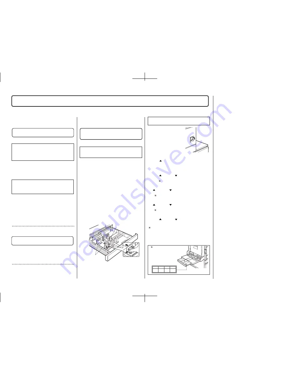
Adjust the position of the paper guides of the
paper tray of B83MP or the upper paper tray of
stand/paper drawer B84LT / B83TT.
Rear guide
Applied model: B83DB
MIN
P1
P2
MAX
Adjust the position of the paper guides
of the bypass tray.
<1> To use the setting mode,
insert the power plug of the main
unit of the printer to the outlet
and turn the main switch on
while pressing the [MENU] key
and the [OK] key of the operation
panel of the main unit of the
printer.
<2> After pressing the [MENU] key several times to
display "SIZE ADJUSTMENT A" in the message display,
press the [
] key to display "SIZE ADJUSTMENT B" and
press the [OK] key.
<3> "MAXIMUM SIZE" is displayed.
Since "MAXIMUM SIZE" is displayed with a number,
press the [
] key or the [
] key to change the number so
that the number is equal to the value of [MAX] written on
the label
(
NOTE
)
and then press the [OK] key.
<4> Since "P1 SIZE" is displayed with a number, press
the [
] key or the [
] key to change the number so that
the number is equal to the value of [P1] written on the
label
(
NOTE
)
and then press the [OK] key.
<5> Since "P2 SIZE" is displayed with a number, press
the [
] key or the [
] key to change the number so that
the number is equal to the value of [P2] written on the
label
(
NOTE
)
and then press the [OK] key.
<6> Since "MINIMUM SIZE" is displayed with a number,
press the [
] key or the [
] key to change the number so
that the number is equal to the value of [MIN] written on
the label
(
NOTE
)
and then press the [OK] key.
[Caution]
If the setting above is not carried out, the paper detection
function will not operate.
"ON"
Label
(
NOTE)
Illustration of label sticking position
(Back surface of the bypass tray
extension)
Then, carry out the off center adjustment.
•
•
Содержание B8300
Страница 1: ......


